Case: 91m High Cavity- Result Of Lacking Geological Study & Support Design?
“Lack Of Investigation may Give Surprise, But Lacking Design Definitely Results In Failure” – Proved Yet Again In Punatsangchhu – II HE Project
– The Case History of Massive Crown Failure In The Huge Cavern. A Perspective Explained Citing Facts, Figures, Analysis & International Technical Literature Of Renowned Authors
A huge cavity of the size of a football field and a height of one third of the height of Eiffel Tower formed through the crown of the 314m(L)x 19m(W) x 58.5m(D) underground cavern of the Downstream Surge Gallery (DSG) of Punatsangchhu-II H.E. Project (1020MW) in Bhutan (PHEP-II), at the time when the cavern was under excavation for 3 years and had been yet excavated to a depth of 35m to 40m. The failed reach of the DSG, assessed originally as ‘fair to good rock mass’, is actually comprising highly jointed and fractured rock-mass of class IV & class-V and acted as the hanging wall formed by the major shear zone with 55ᵒ dip and containing a number of smaller shear zones, which intercepts the DSG and its two adjacent caverns of the PH Complex, throughout their depth. This Shear zone remained unexplored in the original geological assessment.
The Punatsangchhu-II (PHEP-II), a 1020 MW project with scheduled date of commissioning of year 2017 at cost of Rs. 37778 millions, new approved project cost of Rs. 72900 millions ( US $ 1.04 billions), expects further escalation in its cost to Rs. 80000 millions ( US $ 1.14 billions), with already incurred cost of about Rs. 65880 millions, is delayed due to the huge rock mass failure in its underground Downstream Surge Gallery (DSG), resulting in a huge cavity of about 91m height x 70m length and 45m width in the crown of the DSG. The Dam foundations had encountered, a thus far unexplored, mega shear of maximum 30m width, cutting across the length all the 4 dam blocks diagonally. The shear zone with its about 35ᵒ to 45ᵒ dip, continued under the foundations to large depths.
There is a strange coincidence of massive geological surprises and huge rock mass failures, which happened in the two mega hydroelectric projects named Punatsangchhu -I & II H E Projects, under construction since 2009 -10 in Bhutan.
Occurrence of too many geological surprises, the apparent cause of the big mishaps in the two mega Projects, in fact may be a case of ‘ harping on the geological surprises’ as a scapegoat for the lack of proper geological investigations carried out by the Main Consultants for geological assessment to be done by their retained Geology Consultants and inappropriate designs carried out by their retained Designer Consultants.
1. CHANGE FROM A SURFACE POWER HOUSE TO UNDERGROUND POWER HOUSE
Originally in the DPR, the Power House Complex was contemplated to be a Surface Power House, to be located on the right bank at a site 3km downstream from the present location of the Underground PH Complex. The change of PH Complex to underground site selected by the Consultants was based on limited exploration apparently through one borehole DSC1 only as reportedly the additional borehole DSC3 was driven by the Consultants at a different far away location to that was suggested by their own Geology Consultants and the same did not even penetrate through level of crown of DSG and ended much above it besides that the hole was not properly located.
The change of location of the PH Complex to the underground site was made just before the start of construction in 2010. The significant observation by the Geology Consultant, in their geotechnical assessment were stated that, “Rock mass conditions of only limited reach in the DSG have been explored”.
2. GEOLOGICAL ASSESSMENT OF THE UNDERGROUND SITE OF PH-COMPLEX WAS BASED ON AN INADEQUATE GEOLOGICAL INVESTIGATIONS DONE BY THE CONSULTANTS
The location of the additional bore hole DSC3 for the DSG, suggested by the Geology Consultant and drilled during investigation of the site by the Main Consultants, was drilled at a wrong location. The Geology Consultant had in-fact reported that the location of the inclined exploratory hole DSC3, drilled above DSG for geological investigations was not the same as what it had advised to and required from the Consultants.
Thus the rock mass in the DSG crown was not explored at the particular specific location suggested by the Geology Consultant. Also therefore the rock mass comprising the 58m high walls of the DSG too remained to quite an extant unexplored at the location desired by the Geology Consultant.
The Geology Consultant in-fact had reported, in 2010, on the geo-technical investigations done by the Consultants , that less information about the DSG is available for the selected location of power house complex of Punatsangchhu-II H.E.P.
The Geology Consultant’s report stated, “PH Complex is intruded by a number of pegmatite and leucogranite veins/bodies. Five joint sets are prominent which are open to tight in nature, filled with clay and rock flour. The rock in the major reach of PH, TH and DSG cavern is inferred to be FAIR TO GOOD rock as per Q system. Shear/highly fractured zones may be encountered in the Downstream Surge Gallery cavern”. IT further strongly recommended to ” MINIMIZE THE SIZE OF SURGE CHAMBER AS FAR AS POSSIBLE“.
* Therefore as a result, the location of the underground DSG was fixed by the Consultants, based on a geological assessment drawn from a very limited exploration. The geological assessment, later during the excavation, was actually found to be a grossly wrong .
 |
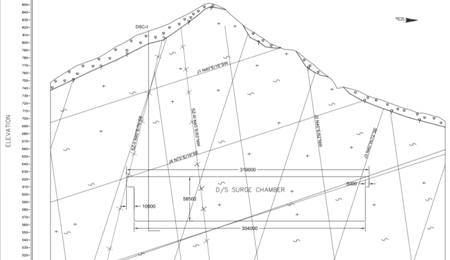 |
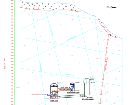
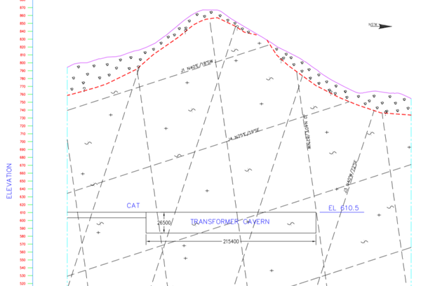
| Tender Drawing of Geological Section Through PH Complex | Tender Drawing of Geological Section Through DSG – Showing the only sole Bore Hole DSC1 being the basis of geological Assessment |
 |
 |
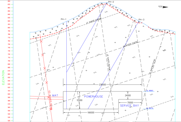
| Tender Drawing of Geological Section Through PH Cavern Showing Bore Holes PH-1, PH-2, and PH-3 |
Tender Drawing of Geological Section Through TH Cavern |
It may be seen that Tender Specification Geological Drawings Show No Presence of Mega Shear Zone, Which Was Later Encountered During Excavation and was found cutting across the three caverns through out their full depths.
3. PROGRESS OF EXCAVATION IN PH-COMPLEX BY FEBRUARY 2016
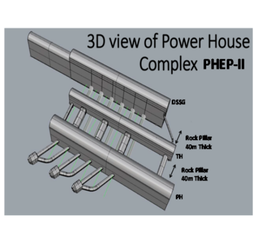
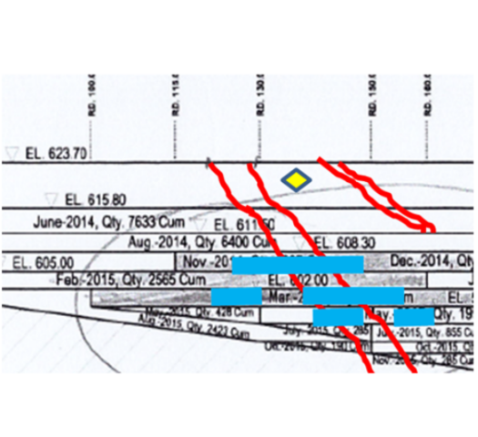
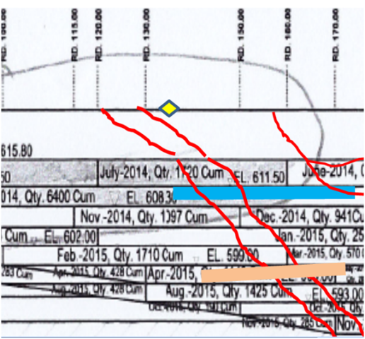
The underground powerhouse complex comprises three large caverns viz. Power House (241m x 23.9m x 51m), Transformer Hall (216m x 14m x 26.5m) and Downstream Surge Gallery (314m x 19.8m x 58.50m) on the right bank of Punatsangchhu River. Excavation of Transformer Hall cavern had been completed to its final depth at EL ±582m, whereas, in Power House/ Machine Hall cavern it was about to completed. The foundation of Turbine Pit -1 with its bottom at EL ±555.84m had already been achieved and rock covering had been done in the Pit. Prior to collapse, excavation of the Down Stream Surge Gallery (DSSG) had reached maximum up to EL ±578m in reaches beyond RD ±210m and in rest of the reaches it was at EL ±593m, including in the failed zone. The DSSG is aligned at N10ᵒE direction for which excavation started in the month of April 2013 by executing its central gullet at its crown at EL ±623.70m, followed by widening of the crown which completed in the month of August 2014.
Initially the proposed length of the DSSG was 210m. Later on, it was extended up to 314m. In the first phase it was excavated from RD 0m to RD 210m with its crown at EL ±623.70m and in the second phase benching was carried out from RD 0m to RD ±210m from springing EL ±615m. The excavation of heading of remaining length of the DSSG, from RD ±210m to RD ±314m, with its crown at EL ±613.70m, was carried out simultaneously.
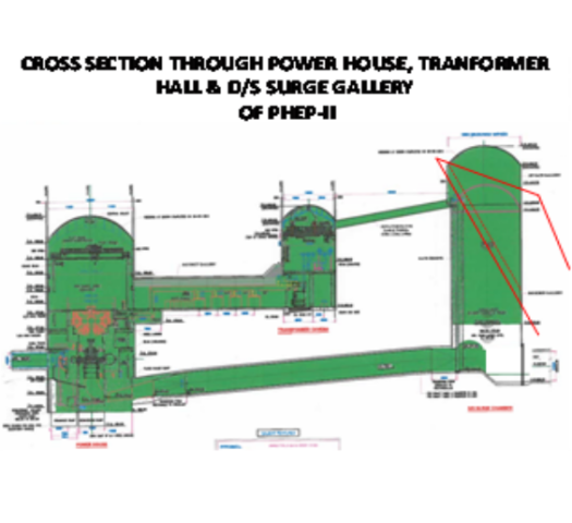
Fig. – 3
Fig. – 4
4. ACTUAL GEOLOGY ENCOUNTERED
The rock mass encountered in the DSG comprises quartzo-feldspathic gneiss, biotite micaceous quartzite with leucogranite and pegmatite patches and veins. Generally due to intrusive nature pegmatite occurs in the form of veins along joints, whereas leucogranite is present in the shape of patches/bands across or along parent rocks. At places leucogranite/pegmatite is crushed / sheared and fractured due to deformation/folded rock strata. In general foliation has gentle dips 10ᵒ-25ᵒ / N205ᵒ-240ᵒ direction and variation in the attitude of foliation is mainly attributed to warping and minor folding. The rock mass encountered in the central gullet falls in class III (40.00%), class IV (50.95%) and class V (9.04%). The class V (Q= 0.19 – 0.58) rock mass mainly occurs in the major shear zone and its vicinity. Major geotechnical problems which were encountered, were occurrence of major shear zone (45ᵒ-60/N030ᵒ) and formation of cavity in the crown during excavation central gullet (RD ±121 to RD ±129m), low dipping foliation joints posing slabbing conditions in the crown portion, erratically occurrence of intrusive bodies of variable dimensions, minor shearing along foliation joints and other joints at few locations. Besides presence of water (seepage/dripping) along shear zone and ingress of water on the right wall between RD 308m and RD ±313.5 (EL ±599m) were main problems.
ROCK MASS CATEGORY ACTUALLY ENCOUNTERED IN THREE CAVERNS :
| CAVERN | FAIR TO GOOD | POOR TO FAIR | POOR | VERY POOR |
| PH CAVERN | NIL | 44.8% | 54.07% | 1.12% |
| TH CAVERN | NIL | 35.65% | 56.94% | 7.4% |
| DSG CAVERN | NIL | 40.0% | 50.95% | 9.05% |
- The rock type actually encountered was ‘very poor to poor and poor to fair’ instead of ‘fair to good’. The same is also confirmed by Norwegian Geotechnical Institute (NGI).
- Geology Consultant’s Assessment Report missed the Shear Zone encountered in central gullet of DSG from RD ±121m onwards dipping 45ᵒ -60ᵒ due N30ᵒ-35ᵒE having thickness ~1.5m-3.5m. The Q value in shear zone reach, from RD ±121m to RD 135m, has been 0.2-0.58 (Class-V).
- Actually DSG encountered 14 nos. of Shear Zones of size 2cm to 3.5m in contrast to only 2 nos. assessed of size 2cm to 60cm.
- 5 nos. of Major Joint Sets including Foliation joint with low dip & direction 10ᵒ-15ᵒ : SW to NW, spacing 0.02 t0 0.3m. Joints, adversely oriented for wedge actions have continuity 10m to 15m are generally altered and stained and showing warping.
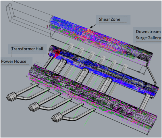
Fig. – 5
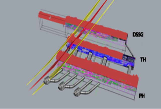
Fig. – 6
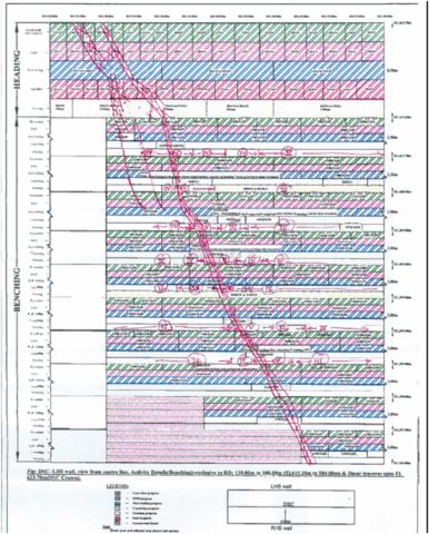 |
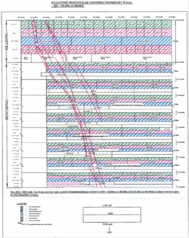 |
| Shear Zone Intercept in DSG U/S Wall From RD 130m to RD 180m | Shear Zone Intercept in DSG D/S Wall From RD 130m to RD 180m |
- The major shear zone (45ᵒ-60ᵒ/N030ᵒ) encountered at the crown portion between RD ±121m and RD ±140m and extending on the either wall dipping towards face (gable end wall) is shown above.
- The hanging-wall portion of the DSG, in its in-situ conditions is propped up by the major shear zone. The Shear Zone reach, from RD 121m to RD 140m, is formed of the rock mass of class- V and the hanging-wall reach beyond RD 140m to RD155m comprise Class-IV, having predominantly Leucogranite with micacious quartzite, biotite gness & pegmatite veins/ bands. Rock mass in this reach is highly jointed and fractured having joints of 10mm to 20mm opening which are filled with clay / crushed material.
5. OVER EXCAVATIONS DURING EXCAVATION OF THE CENTRAL GULLETS IN THREE CAVERNS
Water seepage in the shear zone which further lowered the shear parameters resulted in cavity formation of ~2-7m height in the central gullet of DSG with range of cavity of about 1.55m~ 3.05m at RD 117.0m to 7.87m~7.96m at RD 125.0m to 1.5m~3.5m at RD 138m . Rib supports in the central gullet in the shear affected reach have been provided along with rock bolts of 8m/10m long followed by, additional rock bolts of 12m length provided after installation of rib supports and their back filling and grouting for the full section, as per Designs. Over breaks in these reaches during widening of the Central Gullet remained of the order of 1.0m to 3.0m 0nly.
However, the range of maximum over break in the DSG from RD 138m onwards was of the order of height of only 1.5m to 3.5. This reach from RD 140m to RD 210m is the reach where, later after three years, the huge rock fall has occurred. Incidentally the location of the 8m cavity ,which happened earlier in April 2013, between RD 117m to RD 125m in the DSG, when Shear Zone was exposed in the Central Gullet of the DSG, has remained intact and unaffected from the huge rock fall that happened on 03 March 2016.
The reach of the DSG from RD 140m to RD 210m , which suffered massive rock fall, had witnessed only 1.5 m to 3.5m of over excavation that too only during the excavation of the Central Gullet, as compared to the locations which are intact despite suffering much higher order of over excavations of 8m to 14m in PH and TH caverns and even RD 124m in the DSG itself.
In TH, from RD 84.5m to 95m and then from RD 144.5m to RD 164m, the over excavation ranged from 0m to 5.7m. It ranged from 0m to 5.7m, from RD 175m to 183m and the over excavation in TH it ranged from 0.24m to Max. 7.5m and from RD 190.5m to 207m it ranged from 0m to 13.95m
In PH from RD 116m to 126.5m the over excavation ranged from 0.8m to 3.5m, from RD 137m to 142.5m ranged from 0m to 4.2m , from RD 150m to 159.5m ranged from 0m to 8.2m and from RD 171m to 175m ranged from 0m to 3.8m.
Thus TH and PH caverns experienced much larger sized over excavations i.e. of the order of height of 8m to 14m as compared to the almost entire reach in DSG where the over-excavations remained limited to the order of height of only 1.5m to 3.5m. Both TH and PH through out their entire lengths including locations of as high over excavation as 8m to 14m , with multiple large openings in their walls, are intact .
The only different feature being that the DSG is intersected by the Mega Shear Zone in its crown and also it cuts through entire 58m depth of its walls. The Toe of the Shear Zone got removed during excavation of DSG. Whereas both in the TH and PH Caverns , the Shear Zone is confined and embedded in the Gable End. It does not pose danger in the PH & TH caverns of removal of toe of the Shear Zone there, like the way DSG witnessed it.
- The incidents of over excavation have occurred due to extensive presence of pegmatite veins/ bands and low dipping Foliation joint with dip & direction 10ᵒ-15ᵒ . Excavation in many continuous reaches had not required blasting or was applied with least charge of 0.19 to 0.55 kg/m3. Rock fall due to slabbing action were happening repeatedly .
Incidents of over excavations get explained by the International Research :
* INTERNATIONAL LITERATURE WARNS THAT THE STRUCTURALLY WEAK GEOLOGY IS PRONE TO UNAVOIDABLE OVER EXCAVATIONS
Reference : Forty Years with The Q-System in Norway and Abroad by Nick Barton Eyestein Grimstad :-
- “In underground excavations if the ratio of JN/JR ≥ 6 is encountered ,over breaks are extremely likely to occur despite contractor’s best efforts with careful blasting.”
- In PHEP-II PH Complex caverns the Jn/Jr = 9 to 12
- This explains tendency of over excavations despite use of controlled blasting using charge factor of only 0.6 to 0.8 kg/m3 & even when at many locations merely scooping was used for tunnelling in central gullet.
- The presence of numerous and adversely oriented clay filled joint sets in combination with sub-horizontal foliations and rock mass intervened by pegmatite was bound to result in uncontrolled over breaks.
6. DESIGNED ROCK SUPPORT MEASURES
Rib supports in the central gullet which were extended to full section after side slashing, were provided in the entire reach of all the three caverns of PH, TH & DSG. The rock support measures thus provided as per construction drawings comprise SFRS 200mm thick, 8m/10m long rockbolts and ISMB350 steel ribs @ 0.5m spacing with backfilling of concrete and grouting in the crown for the full section, as per the Designs .
The selected reaches of over excavation were provided by additional rock bolts of 32mm dia and 12m length as advised by the Designers.
The shear zone and its associated zone reaches, in the DSG walls, where it has been exposed, was treated providing concrete cladding, 12m long rock bolts and grouting as per the construction drawing.
- However whether this designed treatment was sufficient to strengthen the rock pillars , provided of just 40m thickness, between multiple caverns situated adjacently and moreover when the pillar is intersected critically throughout its depth and thickness by a mega Shear Zone . The intercept of the Pillar by Shear Zone would have made it a cracked pillar. This Question was best to be answered if and only if a scientific 3D Numerical Analysis of the underground PH Complex would have been done by the Designers incorporating actual geology. However, apparently the analysis was not done by the Designers at that stage.
7. SINKING OF RIBS OBSERVED IN NOVEMBER 2014
During widening of DSG from RD 117.5 m to RD 132m, rock bolts could not be installed immediately after excavation, as the holes were getting collapsed during drilling. hence in order to mobilize immediate rock support, support system of 200mm thick SFRS and Built-up section as per construction drawings were provided and backfilled in this reach. Side slashing /widening of Machine Hall, Transformer Hall and & DSG had been done by adopting controlled blasting and charging technique i. e line drilling, alternate charging of periphery holes. The charge factor observed at site ranged from 0.6 to 0.8 kg/m3 which was considerably low. The rock bolts/wedges had got detached during widening thereby affecting the crown profile and arching action of roof caverns. At some locations in Class III reach of central gullet of these caverns, rock bolts got exposed after loose fall during side slashing. As reported, the geological features are uncertain and of intrusive nature with pegmatite veins, leading to frequent rock fall and accident to men and machinery.
In view of all the above and considering permanent stability of these caverns, it was requested to Consultants a number of times, in fact 29 times between May 2013 to dated 23.12.2013 to suggest adequate supports at the crown of all these caverns before start of excavation in Benching .
During November, 2014, at El. 618.08m, a gap of 55mm had been between ribs and cladding on the D/S wall of DSSC at RD 130m to RD 170m at the location of shear zone and that of 20mm on the U/s wall at RD 170m to RD 180m. The surface target installed on D/s wall showed a sinking of 20mm at springing level. The reaches were cement grouted as advised by the Designers / Consultants after observing no further increase in distress.
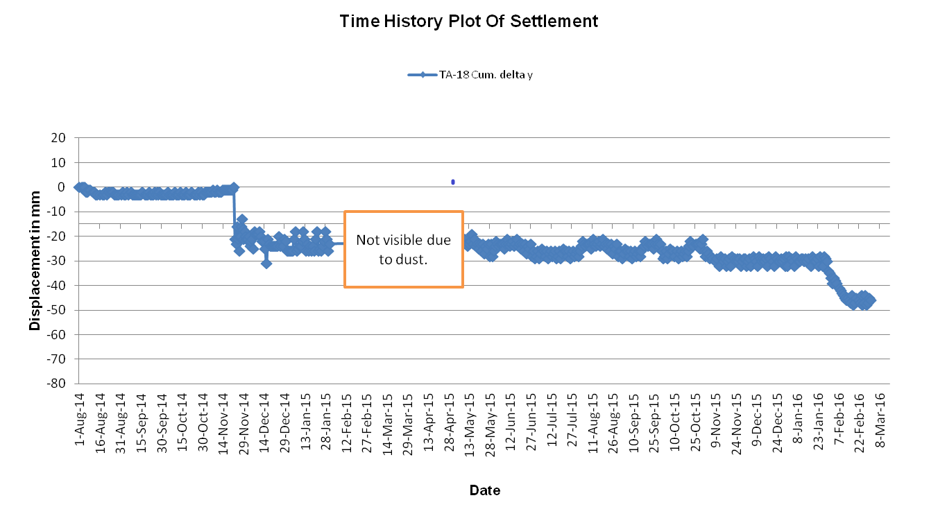
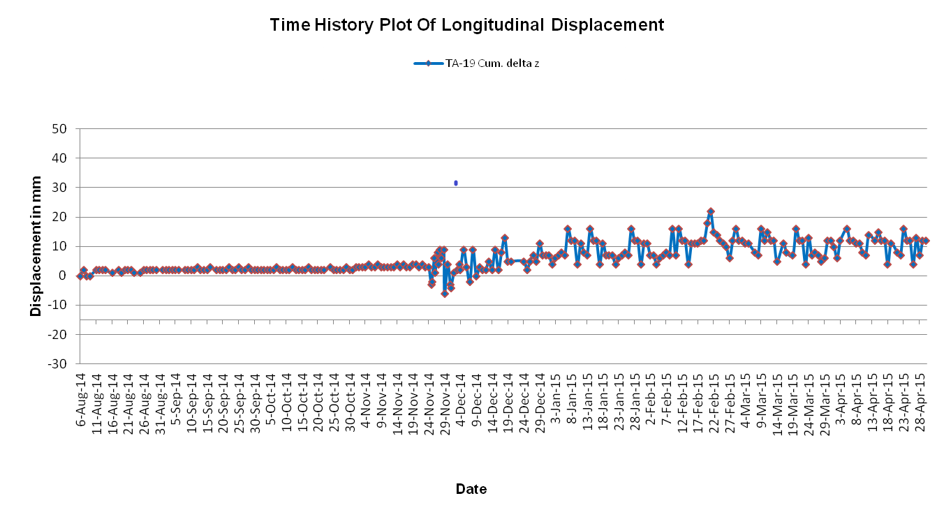
Time History Plot Of Displacements Of Crown At RD 135m :
 |
 |
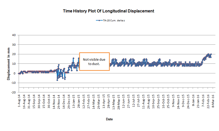 |
| Plot of X- Displacements | Plot of Y- Displacements | Plot of Z- Displacements |
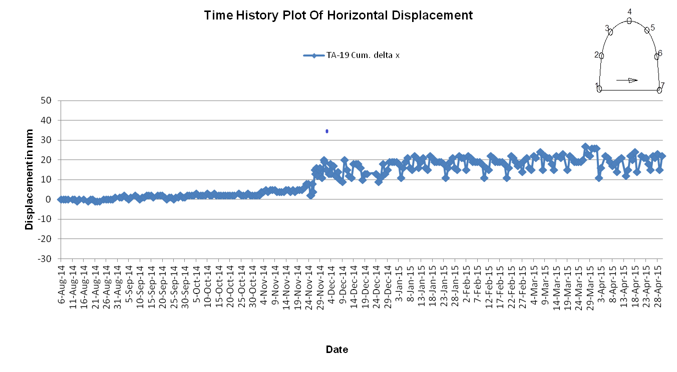
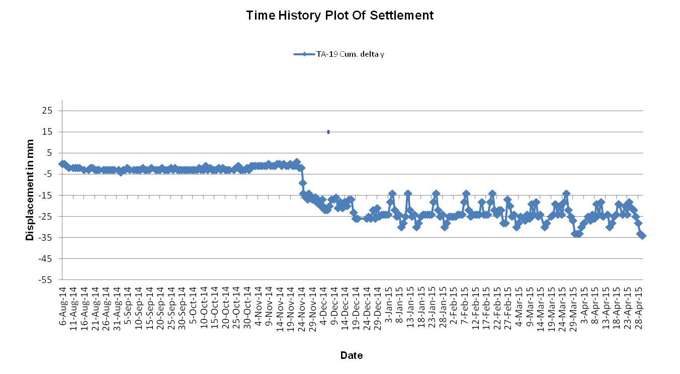
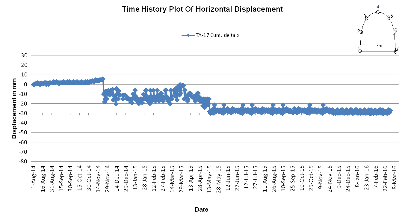
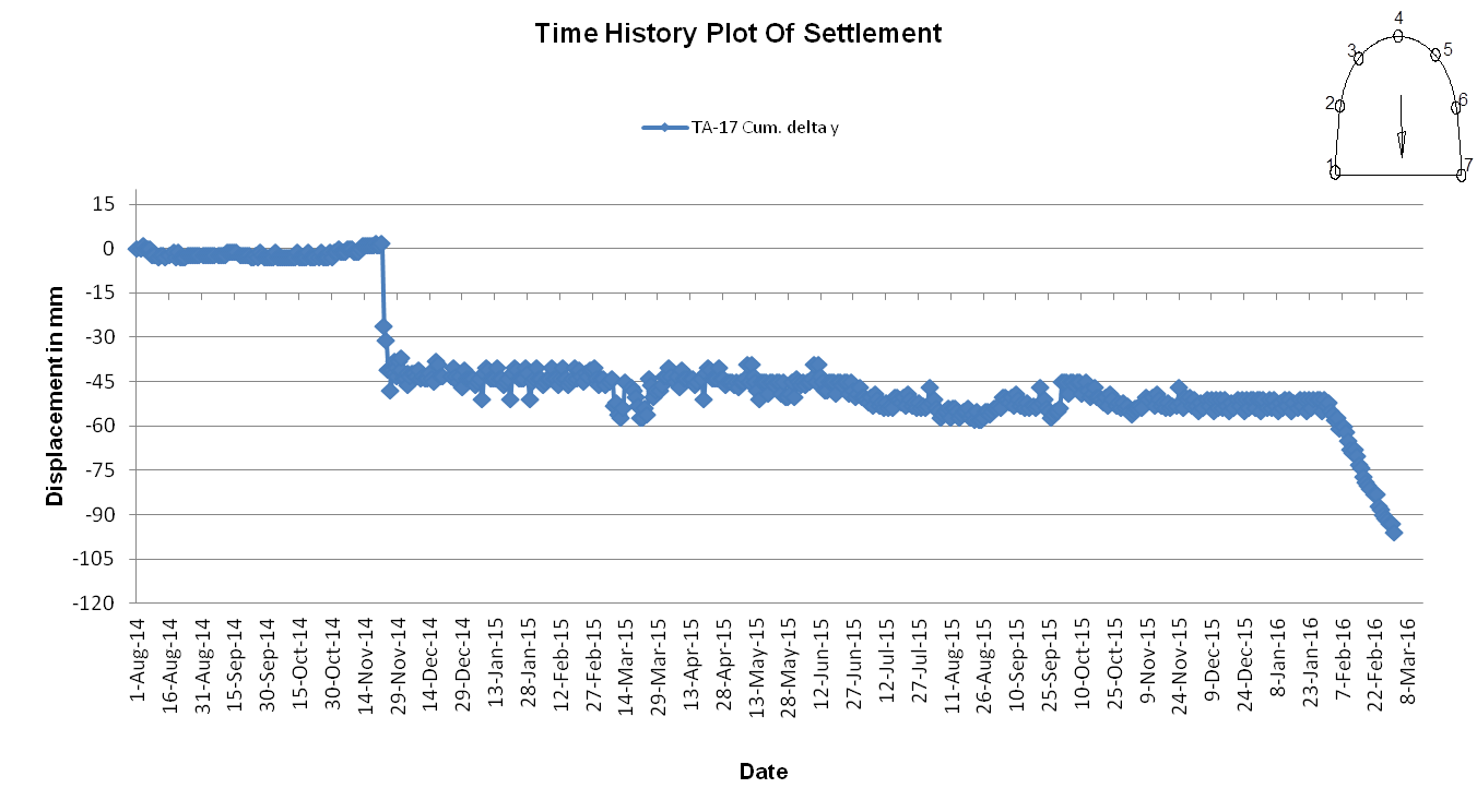
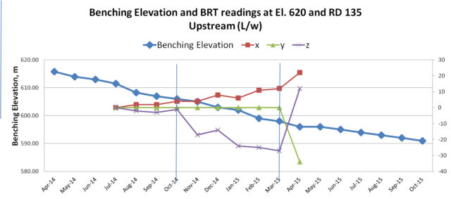
Time History Plot Of Displacements At El. 620m in Upstream Wall At RD 135m
 |
 |
 |
| Plot of X- Displacements | Plot of Y- Displacements |
Time History Plot Of Displacements At El. 620m in Downstream Wall At RD 135m
 |
 |
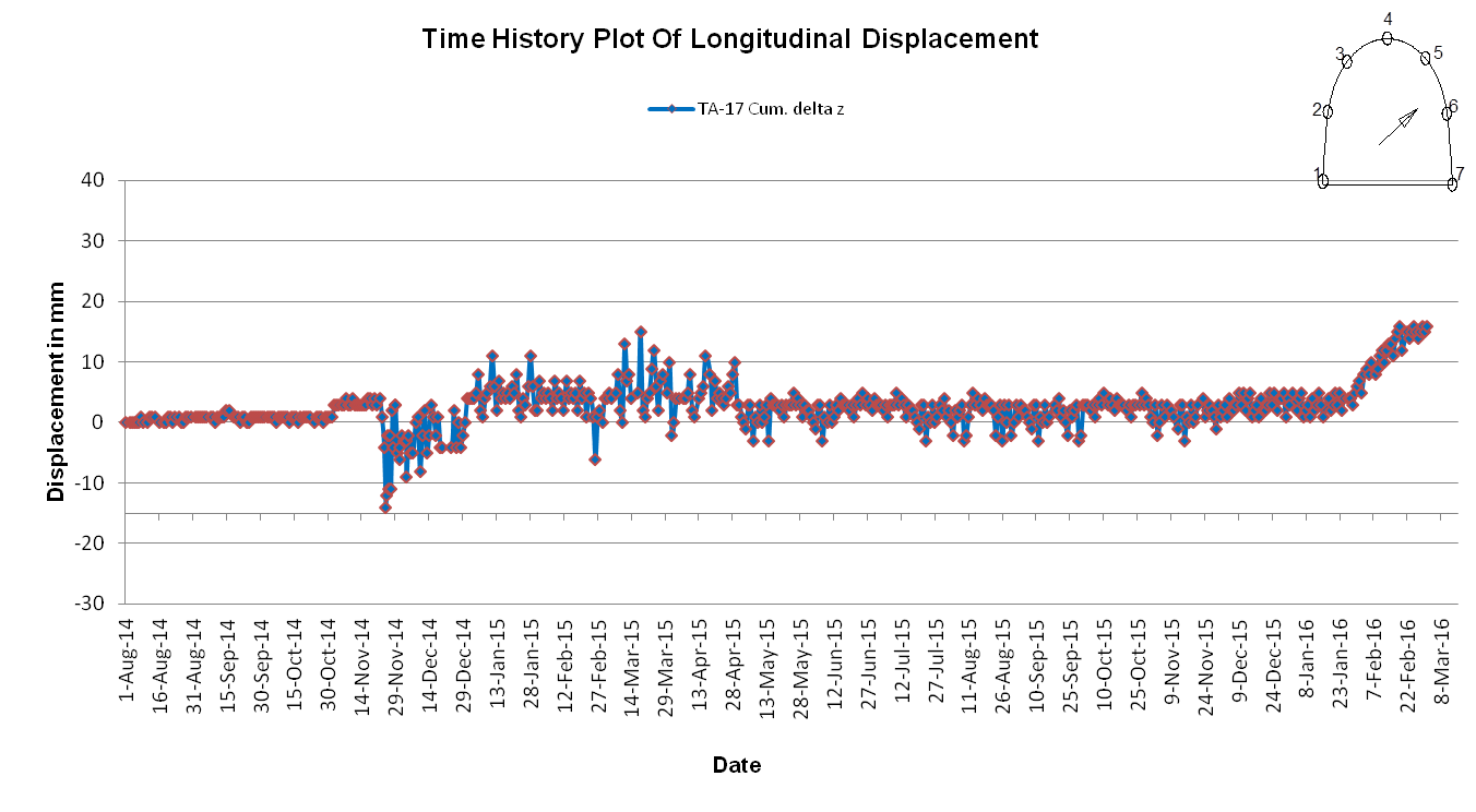 |
| Plot of X- Displacements | Plot of Y- Displacements | Plot of Z- Displacements |
It may be observed from the Time History Plots of Displacements at Crown Level and El. 620m in both Upstream and Downstream Walls of the DSG at RD 135m ( shown above) that a sudden displacement in all the three directions were first noticed on 29 November 2014 in the BRT Surface Target Installed (Location of Target in Crown Shown as Yellow colored in Fig. – 8 below). The displacement kept increasing with sudden sharp increments along progress in Benching.
However, around November 2014 , the location of progress of the excavation in Benching in the reach surrounding RD 135m coincided with the location of occurrence of Shear Zone at the level of Springing of the Rib Arches supporting the crown of the DSG Cavern (Refer Fig. -8 below).
 |
 |
| Benching Excavation In Shear Zone Intercept Reach – D/S Wall of DSG – During Around November 2014 | Benching Excavation In Shear Zone Intercept Reach – U/S Wall of DSG – During Around November 2014 |
8. MAJOR MISTAKES COMMITTED OF NOT TAKING APPROPRIATE MID-COURSE CORRECTIONS IN THE LAYOUT & SUPPORT DESIGNS, RIGHT AT THE STAGE OF START OF BENCHING EXCAVATION, DESPITE BEEN SUGGESTED THE CORRECTIVE MEASURES, AS EXPLAINED BELOW
8.1 The Suggestion Given By The Geology Consultants To Keep Size Of DSG Cavern Smaller By Adopting A Network Of Tunnels And Galleries Of Smaller Size, Was Not Adhered To :
The Geology Consultants had categorically advised to the Main Consultants and the Designers in their 2010 report that, “The Shear/highly fractured zones may be encountered in the Downstream Surge Gallery cavern” and therefore MINIMIZE THE SIZE OF SURGE CHAMBER AS FAR AS POSSIBLE“.
* INTERNATIONAL LITERATURE WARNS THAT POOR GEOLOGY WITH ROCK MASS RATING BELOW 50, IS NOT SUITABLE FOR LARGE CAVERNS
Reference : UNDERGROUND EXCAVATIONS IN ROCK by HOEK & BROWN (Page 299):-
- “The stability of the rock in immediate vicinity of the underground openings in deeper excavations depends upon behavior of the entire rock mass surrounding these openings.
- This rock mass may be so heavily jointed that it will tend to behave like an assemblage of tightly interlocking angular particles with no significant strength under unconfined conditions.
- Therefore Large caverns should only be excavated in rock with adjusted total classification ratings of 50 or better “
* The RQD rating for the DSG stands evaluated of the order of 40 only, which is not favorable for excavation of caverns with larger sized depth. Geological Consultant had also cautioned in their investigation report to not provide large sized DSG.
- However, the Designers / Consultants had provided 314m long x 19.5m wide x 58.5m high single large cavern of the Downstream Surge Gallery (DSG) against the advice of the Geology Consultants.
- The Designers should have reviewed the size of the DSG after the Shear Zone was detected to be intersecting the DSG in its entire depth and relocation of the DSG was not seen possible by them. However the Designers ignored a request made by the Project Management to adopt a set of smaller chambers which shall be interconnected by a network of tunnels. After the rock fall in the DSG, it has become necessary and is being done so to redesign the DSG layout comprising additional smaller chambers and tunnels which make up for the lost volume of the abandoned reach of the DSG.
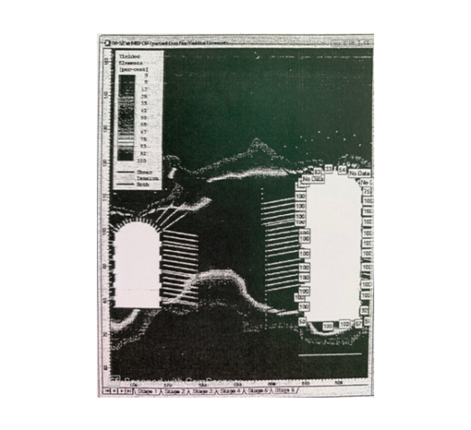
8.2 Results Of Numerical Analysis Informed To The Consultants Indicating Potential Extensive Yielding In DSG Walls In Shear Zone Affected Reach Was Ignored :
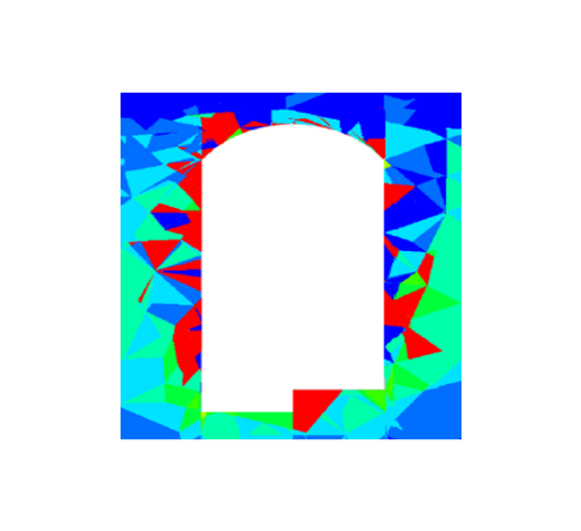
After, the gap of 55mm that occurred between ribs and cladding on the D/S wall of DSSC at RD 130m to RD 170m at the location of shear zone and the gap of 20mm on the U/s wall at RD 170m to RD 180m, in the DSG at El. 618.08m along with sinking of the ribs by 20mm at springing level in the November, 2014, the Contracting Agency responsible for construction of the Power House Complex had carried out a Numerical Model Analysis of the DSG cavern. The analysis established that when the DSG excavation reaches 2/3rd of its depth, there would be wide spread yielding of rock mass occurring in the walls of the DSG. It established that with further progress of the excavation to its full depth of 58.5m, the yielding of rock mass would be 100%.
 |
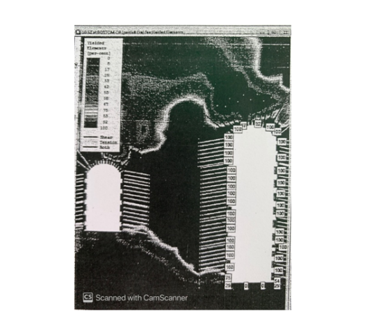 |
| Yielded Zone of Rock Mass in The Rock Pillar When DSG is Excavated to 2/3rd of its Height | Yielded Rock Mass in The Rock Pillar When DSG is Excavted to its Full Height |
- The results of the analysis were informed to the Designers Consultants , but they did not agree with the findings of the analysis performed by the Contracting Agency and ignored the same.
8.3 The Suggestion To Provide Wall Beam Over The Shear Zone And Providing Of Cable Anchors Was Not Adhered To:
Based on the findings and results of the above mentioned Numerical Analysis, it was suggested by the Project Management to the Designers to provide Wall Beam at El. 608m. It was also suggested to the Designers to design appropriate Cable Anchors to strengthen the crown and walls of the DSG in the reach affected by the Shear Zone.
- However the provision of Wall Beams and Cable Anchors was not agreed to by the Designers.
8.4 The Layout Design Of The Three Caverns Which Needed To Be Changed To Provide Thicker Rock Pillars Between The Adjacent caverns Was Not Done :
PHEP-I is the nearest located H E Project at 11Km in the U/S of PHEP-II and both have almost identical layout. Incidentally, both PHEP-I and PHEP-II have been contemporary in their designs and construction by the same Designers and Consultants.
As the rock mass in PHEP-II underground DSG has been Class –IV (poorer, which is further weakened due to its intersection by major Shear Zone at 55ᵒ dip, in comparison to that of Class – III (better rock class) in PHEP- I, therefore the Pillar/ wall width in case DSG of PHEP-II, logically, should have been kept larger than pillar width provided in PHEP-I of 40m ( refer Fig. – 1 given earlier above).
Further, In case of PHEP-I, the thickness of rock pillar / wall between PH and TH cavern is 52.5m , which is equal to depth of the PH cavern there in PHEP-I. On that lines thickness of the rock pillar / wall between TH and DSG of PHEP-II, logically, should have been 58m i.e. equal to the depth of DSG , instead of the presently provided thickness of 40m.
* The principal of providing thickness of the rock pillar equal to the depth of the cavern with larger depth of the adjacent two caverns is recommended also by the following International research :
* Reference : Design of large underground caverns – paper by Cheng Y and Liu , Taiwan, – 6th Cong. ISRM, Montreal :
- ” The pillar width between two caverns should be equal to or more than the depth of the cavern with larger depth of the two”.
- Out of the adjacent caverns of DSG and TH , the DSG is of larger depth that of 58.5m. Thus the rock pillar between TH and DSG should have been at least 58.5m thick. In fact because a major shear zone is intersecting this pillar, the thickness of the rock pillar provided should have been still bigger than 58.5m was
- However the 40m thickness of the DSG Pillar was fixed or designed, if at all on the basis of some design, it must have been done so, prior to coming to know of both the actual poor geology and the intersecting shear zone. Therefore 40m thickness of the pillar being already lacking the thickness as stipulated by International Researches, had in fact become further weak due to its intersection by the Shear Zone.
- This stand gets vindicated by the results of the 3D Numerical Model Analysis done by an independent agency of repute, to study behavior of the original designed layout of the three caverns under actual geological conditions and without incorporating any over excavations (Refer Paragraph No. 12 below). The analysis, which had not included any effect of over excavations accounted for, yet establishes that, the DSG walls, along the intercept made by the shear plane, in fact had already yielded up to 10m to 15m depth in the 40m thick rock pillars at haunch level of the crown and below, over a large length of the DSG walls, in the reach RD 140m to RD 210m , in the hanging wall side of the shear zone where throughout this reach the shear zone intersected the rock pillars/ walls of DSG.
- It is certain that if a scientific analysis was ever done originally by the Designers to fix the layout and thickness of the pillars / walls kept between the adjacent caverns of the underground PH Complex, the safety and stability of the DSG cavern with the provided thickness of rock pillars, under actual poorer geological conditions and the presence of the intersecting Shear Zone, would have been seen to be failing with progress of excavation in benching.
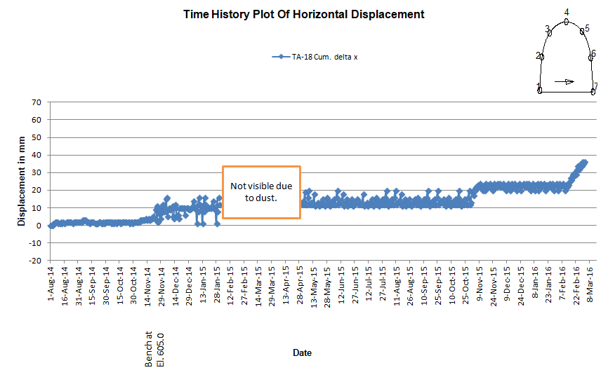
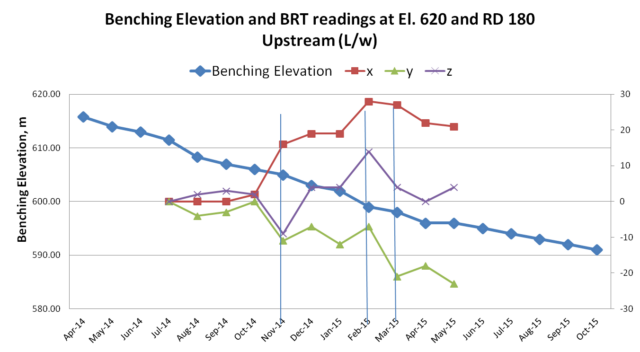
9. PLOTS OF DISPLACEMENTS AT RD 135m & RD 180m SHOW THAT THE DISPLACEMENTS WERE INCREASING WITH PROGRESS OF BENCHING
 |
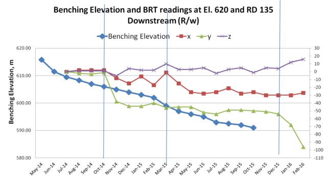 |
| Plot of Displacement in the Upstream Wall At El. 620m in the Crown Arch of DSG at RD 135m | Plot of Displacement in the Downstream Wall At El. 620m in the Crown Arch of DSG at RD 135m |
 |
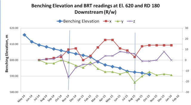 |
| Plot of Displacement in the Upstream Wall At El. 620m in the Crown Arch of DSG at RD 180m | Plot of Displacement in the Downstream Wall At El. 620m in the Crown Arch of DSG at RD 180m |
It may be observed from the above Plots of Displacements at RD 135m and RD 180m, that the displacements were increasing with the progress of excavation in Benching, despite the walls having been supported with the designed rock support system.
The rock mass in the wall, beside been intersected by major Shear Zone dipping 45ᵒ -60ᵒ due N30ᵒ-35ᵒE having thickness ~1.5m-3.5m, comprise Quartzo feldsphatic biotite gneiss / biotite gneiss/ micaceous quartzite with leucogranite & pegmatite, minor shear seams , thinly foliated rockmass with low dip[ping foliation (10ᵒ – 25ᵒ / N200ᵒ – 230ᵒ) joint at places.
The general rock support system provided in the walls, as per drawings, comprise 8 – 10m long rock bolt ( 36 mm dia.) @ 1m/ 1.5m C/C & SFRS 200mm thick.
The reach in walls in Shear zone and associated weak rock mass has been supported with concrete cladding and two sets of 15m long 36mm dia rock bolts followed by consolidation grouting. Out of the two sets of rockbolts provided for cross stitching the shear zone, one set of rockbolts driven from South to North direction were ending entire part of their anchorage length in the shear zone/ class IV fractured rock mass. Wire mesh with consolidation grouting has been provided in the vicinity areas of shear zone having fractured / crushed rock mass. At places minor seepage has been observed along shear zone and its vicinity.
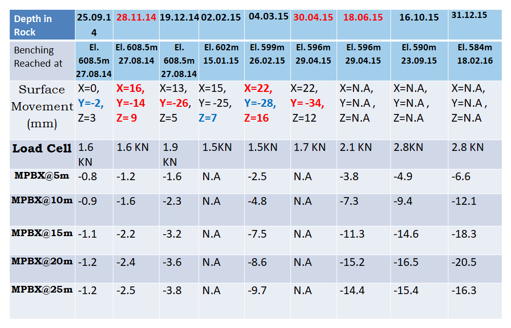
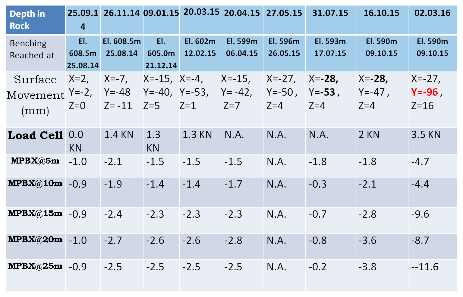
10. THE OBSERVATIONS OF INSTRUMENTATION IN DSG
With the Benching progressing deeper, the reach in the Hanging Wall comprising fractured rock mass suffered subsidence and drifting with increased dilation due to increased depth of excavation.
- By 31.12.2015 when the benching proceeded to El. 587m in U/S wall and to El. 590m in D/S wall, the distress observed by MPBX in the crown remained insignificant. While distress in the U/S wall at Rd 135m at El. 609m got to the order of 5 to 8mm and that in the D/S wall increased to the order of 13.4 mm. While the distress observed by MPBX at RD 180m at El. 609m in the U/S wall had increased to 21.4mm and that in D/S wall had increased to the order of 27.5mm.
- The important and much significant phenomenon observed is that ever since the benching had proceeded , the MPBX readings remained insignificant , thereby indicating that the displacement shown by the Surface Target meant that the rock mass above crown of the DSG cavern (at least up to a thickness of at least 25m of the rock above crown i.e. up to end of MPBX length) and the portion of walls lying above the intercept of shear plane, behaved like one body.
- This upper truncated portion of the cavern separated along the inclined Shear plane and continuing in the walls of DSG towards North from the shear zone, had apparently started sliding bodily on the shear plane which dipped steeply from South to North direction and also dipped in other plane from U/S side wall to D/S wall.
- The bodily movement of this truncated portion, along the shear plane is evident from the observation that while the MPBX readings remained insignificantly small, the Surface Target observed movement had been increasing very significantly.
- The readings shown by the MPBX instruments installed near the locations of collapse were almost constant for last 10 months and showed sudden increase in their readings on 02nd Mar, 2016. The reading of instrument installed at RD 135 at crown level (centre of the cavity) at El. 623.5m which was also constant till 01st March 2016 showed sudden increase from -0.5 mm to -1.0mm at 25m depth, -0.6mm to -36.7mm at 15m depth, -0.5mm to-27.5mm at 10m depth and -0.9mm to -9.8mm at 5m depth.
- On 02.03.2016, the crown at RD 135m had drifted in direction from U/S to D/S walls by 36mm , had sunk by 46mm and drifted in direction from South to North direction by 20mm along the two dip directions of the shear plane.
- At this time, on 02.03.2016 at RD 135m in crown the distress recorded by MPBX too had suddenly increased from less than 1mm earlier to 36.7mm sinking and at around 1.00am , the crown apparently due to failure of arch toe at SPL and below in a reach in which the Shear Plane intersected walls.
11. THE MASSIVE ROCK FALL – HAPPENED ON 03 MARCH 2016
Massive rock mass failure happened from crown in Downstream Surge Gallery (DSG) between RD ±140m and RD ±210m, apparently, along a major shear zone (45ᵒ-60ᵒ/N030ᵒ) encountered at the crown portion between RD ±121m and RD ±140m and extending on the either wall dipping towards face (gable end wall). The failure of rock mass took place within a short period, starting on 3rd March, 2016 around 1.00am, leading to formation of huge cavity above crown. Six technicians working, at the time of the rock fall, in the DSG at locations between RD 140m to RD 210m, got buried under the falling rock muck and died. Bodies of only 3 of the dead were retrieved after removal of some muck from the toe of the piled up fallen muck.
The loose fall from cavity had not stopped completely after the collapse on 03 March and intermittent loose fall continued for some three weeks. Rock After 03 March, the other loose fall from cavity had been recorded on 11/03/16 (Photo-2) and 22/03/2016. A portion of the cavity and hanging rock bolt became visible through a gap formed, after muck from top of the heap rolled down when some rock muck was removed from bottom at toe of the heap (Photo-3) in making efforts to retrieve dead bodies of the entrapped persons. The impact of the rock fall incident had been noticed in the nearby caverns/structures in the form of development of new cracks in the shotcrete, widening of already existing cracks particularly on the right wall of TH and Bus Ducts nos. 2 and 3.
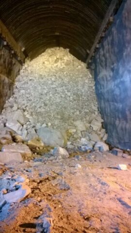 |
Which Blocked DSG At RD 140m
Photo – 1
The construction Adit opens in the southern side of the DSG. The northern side of the DSG did not have any independent access. The northern half of the DSG got cut off from the southern side of DSG as the fallen muck blocked the DSG at RD 140m. Ten technicians who were working in the northern end of the DSG at the time of rock fall, miraculously escaped, after climbing the 45m high rock muck heap, from the small opening left at the top of the heap. However the small opening from where these ten technicians escaped had got blocked with further rock fall soon after they escaped.
The fallen rock mass comprises variable size of fragmented rock pieces, sandy clay and dry clay fractions with big rock blocks (max. size ~9.0m x 1.5m x 3.0m). This clearly indicates that failure of rock mass is not restricted to only shear zone and its associated weak material, but the rock fall has been resulted from the loose fall, controlled by the gravitational forces acting on the blocks of rock comprising the rock mass and making them fall down as these disintegrated from adjoining blocks for being held together only weakly due to presence of clay content and crushed material in their joints and due to presence of intrusive pegmatite veins / bands.
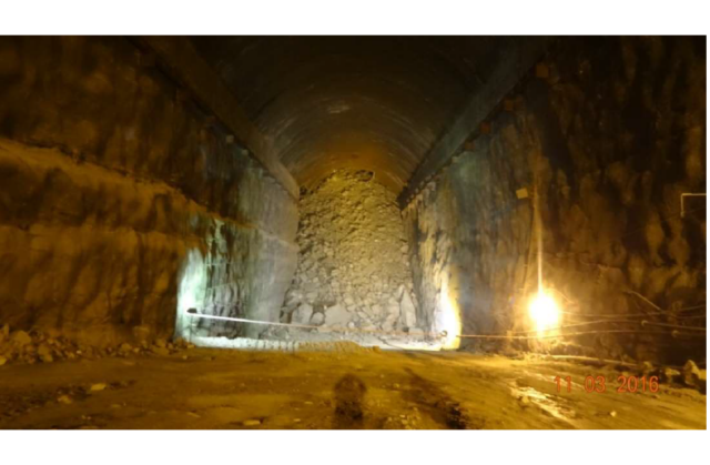 |
Photo – 2
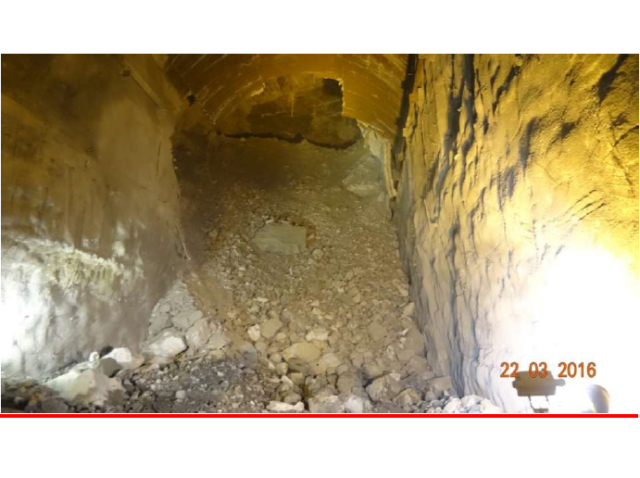 |
Photo – 3
12. THE ASSESSMENT OF THE SIZE & ORIENTATION OF THE CAVITY FORMED
The size of the cavity and its orientation was assessed from a number of exercises including Seismographic Tomography, Lidar based Cavity monitoring using CMV 500 camera lowered from two number of 250mm dia holes drilled from ground surface above the location of cavity and a few holes done from the Cable Tunnel running parallel to the DSG.
The above mentioned studies revealed that the massive rock mass failure which took place in very short time, did lead to formation of a huge cavity of 91m height x 45m width x 70m length above crown of the DSG Cavern.
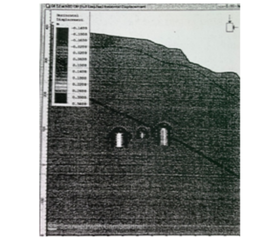
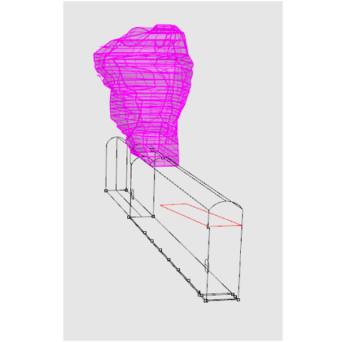 |
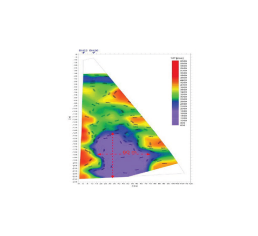 |
| 3D View Sketch Of The 91m High x 70m Long x 45m Wide Cavity Formed Above DSG Cavern | Result Of Assessment Of The Cavity By Tomography |
13. A Thorough Analysis Was Required To Check The Design Of Layout Of The Three Caverns For The Structural Stability, Under Conditions Of Actual Geology Including The Mega Shear Zone. If It Had Been Done Before Progressing With Excavation In Benching, It Would Have Established That Deeper Excavation Would Result In Widespread Yielding Of Rock Mass & Collapse :
The rock mass in the DSG in the Hanging Wall side of the Shear Zone in the DSG comprise thinly foliated, highly fractured biotite gneiss and crushed leucogranite/pegmatite.
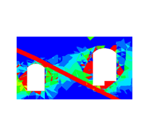
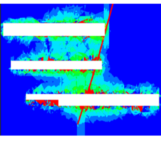
A 3D Numerical Model Analysis done by an independent agency of repute has established that the rock mass lying over the Shear Plane from RD 145m to RD 195m suffered yielding, up to a thickness of about 10m to 15m inside the rock Pillar and the walls, while the DSG had been excavated only to about 45m of its full depth of 58.5m.
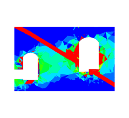 |
 |
 |
| Rock Mass in DSG Pillar Yielded Up To 15m Thickness At RD 145m | Rock Mass in DSG Pillar Yielded Up To 15m Thickness At RD 155m | Wide Spread Yielding Of Rock Mass Around DSG At RD 195 |
 |
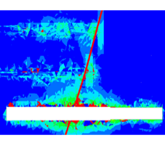 |
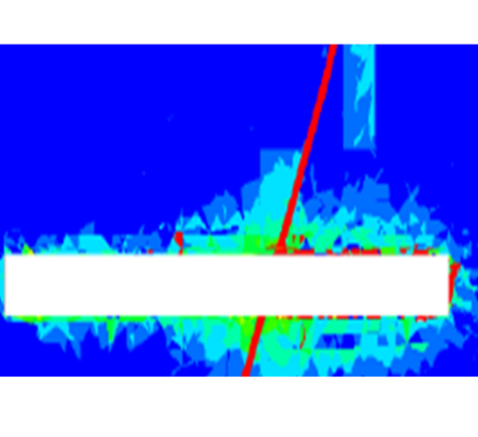 |
| Wide Spread Yielding Of Rock Mass Around DSG At EL. 600m | Wide Spread Yielding Of Rock Mass Around DSG At EL. 610m | Wide Spread Yielding Of Rock Mass Around DSG At EL. 620m |
14. The Possible Explanation Of The Phenomenon Leading To The Massive Rock Mass Failure
- Surface BRT Readings v/s MPBX Distress Readings At Crown At RD 135m:
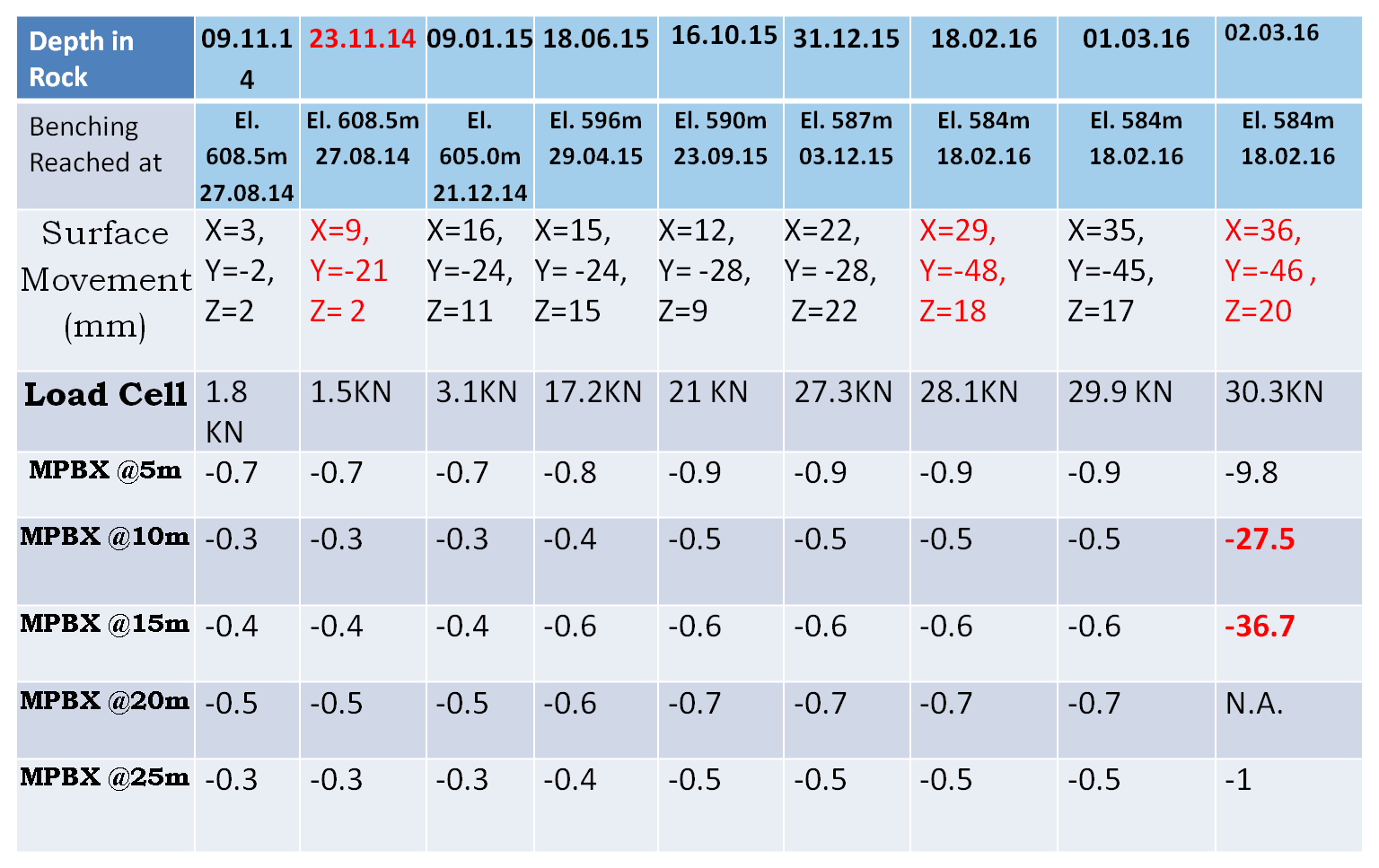 |
- The reading of MPBX instrument installed at RD 135 at crown level at El. 623.5m which was constant till 01st March 2016 showed sudden increase from -0.5 mm to -1.0mm at 25m depth, -0.6mm to -36.7mm at 15m depth, -0.5mm to-27.5mm at 10m depth and -0.9mm to -9.8mm at 5m depth, When the Surface BRT Instrument showed the crown having displaced in X-Direction from Upstream to Downstream wall side by 36mm, Y- Direction (Settlement) by 46mm and Z-Direction towards Northern Gable end by 20mm .
 |
 |
| Surface BRT V/s MPBX Readings At EL. 620m In Crown At RD 135m In Upstream Wall | Surface BRT V/s MPBX Readings At EL. 620m In Crown At RD 135m In Downstream Wall |
The reading of MPBX instrument installed in the crown arch at RD 135 at El. 620m in Upstream Wall which was not very significant till Jun 2015 started increasing thereafter and became quite significant by Oct 2015 and the distress still increased reaching to the order of 20.5mm and in the Downstream wall side MPBX at El. 620m at the RD 135m the distress which was insignificant, it increased suddenly on 02 March 2016 to 11.6mm, When the Surface BRT Instrument showed the the arch at El 620m having displaced in X-Direction Upstream to Downstream wall side by 27mm, Y- Direction (Settlement) by 96mm and Z-Direction towards Northern Gable end by 16mm .
* Reference : Under Ground Excavations in rock by Hoek & Brown/ page 210
- “In case of an inclined over-body, the shear stress being parallel the dip of the over-body, gives rise to asymmetrical stress distributions. This asymmetry is even more pronounced when excavations are influenced by gravitational loading (from structurally poor rock mass matrix)”.
- Norwegian geotechnical institute, which was assigned to suggest strengthening measures after rock mass failure, has in its report mentioned that “in the area of cavity in DSG ( i.e. Shear zone affected area), the pillars are more loaded” . (i.e. Indicating loaded beyond their capacity )
It has been noticed that in the shear zone thinly foliated, highly fractured biotite gneiss and crushed leucogranite/pegmatite is exposed particularly on the left wall near SPL at RD 124m to RD 140m . Further at the crown near RD ±170m blocky and jointed rock mass is exposed.The rock mass quality in PHEP-II is Poor to Very Poor formed of fractured and blocky rock mass comprising Quartzo feldsphatic biotite gneiss / biotite gneiss/ micaceous quartzite with leucogranite & pegmatite, minor shear seams , thinly foliated rockmass with low dipping foliation (10ᵒ – 25ᵒ / N200ᵒ – 230ᵒ) joint at places. The major shear zone (45ᵒ-60ᵒ/N030ᵒ) encountered at the crown portion between RD ±121m and RD ±140m is extending above the crown and below on the either wall dipping towards face (gable end wall).
- The massive rock mass failure took place in very short time leading to formation a huge cavity above crown (Fig. – 11). The fallen rock mass comprises variable size of fragmented rock pieces, sandy clay and dry clay fractions with big rock blocks (max. size ~9.0m x 1.5m x 3.0m) which clearly indicates that failure of rock mass is not restricted only to shear zone and its associated weak material.
* It can be explained that the shear zone material and associated weak rock mass fell down first. Later on the jointed and blocky rock mass, which was abutting along the plane of the shear zone and structurally being just an assemblage of rock blocks, it was bound to slide/fall down under its gravitational force due to removal of its toe. Large blocks of parent and intrusive rocks fell down (intermittently) for the last 20 days resulting into formation of huge cavity (±50m) above the crown (EL ±623.70m) tentatively between RD ±130m & RD ±170m. The lateral and vertical extension of cavity towards gable end wall is because of slabbing and wedge.Large blocks of parent and intrusive rocks kept falling down subsequently as the cavity propagated in its height to 91m, in length to about 70m and in width to about 45m.
- The Norwegian Geotechnical Institute has mentioned in its findings that the ribs do not show any sign of deformation and the rock pillars are more loaded. The fact that failed/fallen ribs do not show any sign of deformation (bending/shearing/twisting), clearly indicates that ribs have failed due to sudden impact of overlying dead load, which was resulted from settling of the yielded rock mass in the Pillars and thus failing the toe of the ribs at SPL.
- The toe of the ribs rested on the yielded rock pillars which were already weak because of their provided thickness of 40m only, which was less than the norm of thickness advised by International Research Papers and as such required to be 52m. Further the pillar were weakened by the intersecting mega shear zone. Therefore with the sudden impact of sudden development of the dead gravitational load in the crown due to sinking of its supports , the toe at SPL of the ribs failed.
15. THE CRUCIAL REVIEW WHICH WAS MISSED BY THE DESIGNER/ CONSULTANTS, WOULD HAVE WARRANTED SHIFTING OF DSG OR ALTERING ITS LAYOUT TO AVOID ITS INTERSECTION BY THE SHEAR ZONE
A critical decision about the site of the PH Complex, which was required to be reviewed by the Designer / Consultants at the time when the site conditions and the encountered geology were reported to the Designers/ Consultants time after time, is discussed below citing reference from the International Literature of the renowned author :
 |
| Conceptual Visualization Of Shear Zone Cutting The Hill |
15.1 The Shear Zone encountered in the Construction Adit of DSG & Main Access Tunnel to the PH Cavern earlier in 2013 were indicative of its intersection of the three caverns :
The shear zone along which apparently, the failure of rock mass has taken place had been identified prior to excavation of DSG and it was delineated in Adit to DSG (at RD ±440m) and Main Access Tunnel (at RD ±420m) in the year 2013.
15.2 The same shear zone when was encountered in the crown of DSG between RD ±121m and RD±129m, the Project Authority advised the Designers / Consultants to shift the location of all the three caverns of PH, TH & DSG to avoid their intersection by the Shear Zone :
During excavation of central gullet of DSG the same shear zone was encountered in the crown of DSG between RD ±121m and RD±129m at crown level (EL ±623.70m). The Resident Geologist, at that time, made an assessment of the intersection of this major shear zone and influence of its associated zone. Taking note that the steeply dipping Major Shear Zone will be cutting the PH and TH that too for their entire depth, the Project Geologist suggested for shifting the location of all the three caverns, to avoid their intersection by the Shear zone.
However as per the instructions of the Designers / Consultants, only the Machine Hall and Transformer Hall caverns were shifted towards backwards (N190ᵒ direction). Along shear zone water seepage had also been recorded (central gullet) which had lowered the shear parameters. The shear zone (attitude; 45ᵒ- 60ᵒ/N030ᵒ) has associated rock mass classified as class V (Q – 0.19 – 0.58). Over breaks of the order of 4.0m to 8.0m were observed between RD ±121m and RD ±129m in the Central Gullet. During excavation of central gullet a cavity (7m-8m) was formed at crown level and it was back filled with concrete and rock mass grouted before widening. The entire zone was supported with steel ribs.
During slashing/widening of the DSSC no adverse effect such as cavity formation, distressing in rock mass and disturbance/deformation in already erected ribs were noticed / recorded.
However, during November 2014, when the benching was progressing in the Shear Zone and its affected zone, sinking of the steel ribs at SPL line were noticed on the DSG wall near shear zone and it was communicated to the Designers/ Consultants. The gap created in the concrete pad and the rock profile in the affected reach was filled back and grouted as advised by the Designers / Consultants.
* INTERNATIONAL LITERATURE WARNS THAT : “STEEPLY INCLINED STRUCTURAL GEOLOGICAL FEATURES & FAULTED /JOINTED ROCK MASS MAY WARRANT RELOCATION”
* Reference : UNDERGROUND EXCAVATIONS IN ROCK by HOEK & BROWN (Page 10 & 11):-
- ” Instability due to adverse structural geology tends to occur in hard rocks which are faulted and jointed and where several sets of discontinuities are steeply inclined. Stability can sometimes be improved by relocation or reorientation of the excavation but fairly extensive support is usually required. Rockbolts, dowels and cables are particularly effective, provided that the structural features are taken into account in designing the support system.
- If stability cannot be improved by reorientation / relocation and design of support to prevent gravity falls to reinforce potential fracture zones is not possible, the SITE BE REJECTED. “
- Taking note that the steeply dipping Major Shear Zone will be cutting the PH and TH that too for their entire depth, the Project Geologist suggested for shifting the three caverns, to avoid their intersection by the Shear zone.
- The Design Consultants shifted only the PH & TH caverns to avoid major Shear Zone from intersecting these caverns.
- Designers still preferred the huge sized single gallery. The site of DSG was neither rejected nor bifurcated or shifted to avoid shear zone and the fractured zone
- Provision of cable anchors suggested by Project Authority for improving structural stability were specifically denied by Design Consultants
CRUCIAL ACTION REQUIRED BUT MISSED WAS:
As the major shear zone was to intersect all the three caverns throughout their entire depth, thus beside shifting the location of TH & PH, it was also prudent to at least bifurcate the DSG in to two chambers with the middle reach of DSG from RD 130m to RD 180m intersected by shear zone, been left un-excavated. Additionally small interconnected galleries could be provided to make up for volume lost in thus abandoned middle reach.
16. IS THE PRESENT SITE OF THE PH COMPLEX OF PHEP-II SAFE ??
Actually in the DSG which is aligned in North-South direction, the Shear Zone cutting it across, separates a relatively good rock mass occupying in its southern side, from a fragmented rock mass with sub-horizontal foliation, intruded with lenses & inter-bedding of altered & weak material like crushed pegmatite occupying its northern side.
The rock mass in the DSG Occupying its northern side of the partition made by the Shear Zone, behaved like an assemblage of loosely packed rock blocks forming the hanging wall, which when were rendered unconfined along its face abutting the Shear Zone and crown surface , were bound to slide/fall down under its own gravitational load, due to removal of its toe. Large blocks of parent and intrusive rocks fell down (intermittently) for the 20 days resulting into formation of huge cavity (±91m high) above the crown (EL ±623.70m) tentatively between RD ±140m & RD ±210m. The lateral and vertical extension of cavity towards gable end wall is because of slabbing and wedge formations.
However, the most important point is that after the sudden formation and fast propagation of the cavity to a height of 91m and its spread in about 70m length and about 45m width, the huge cavity and its surrounding rock mass is lying, for more than 4 years, unattended and untreated and without getting strengthened. What would be the condition of the rock mass surrounding the cavity ? The Tomography study indicates that a bigger zone surrounding the profile of the cavity is disturbed.
What should be the extent of strengthening the rock mass surrounding the cavity and the walls of caverns of the DSG, TH and PH so as to make this site safe for about 100 years of the life of the Project ??