“When Prime Minister Shri Narendra Modi does the ‘Pran Pratishtha’ of Shri Ram Lalla’s idol at Ayodhya, he would be representing every citizen of our great Bharat”.
“Shri Ram embodies the spirit of India. The true spirit of India and Indianness is discipline, truth, honesty, ethics, moral values, acceptance and celebration of diversity, respect for elders, strong family bonds and all such fine human values“
SHRI RAM MANDIR – Fulfilment of a divine dream The Original Unedited Article by Shri Lal Krishan Advani
I am elated beyond words that we are on the verge of realising my most cherished dream of having a grand Shri Ram temple at Ramjanmabhoomi, the birthplace of Shri Ram.On 22nd January 2024, Prime Minister Shri Narendra Modi will install the idol of Shri Ram at the beautiful temple in Ayodhya, and I feel blessed that I will witness this historic occasion in my lifetime.
PM Modi greets Shri LK Advani on his Birthday every year
I have always believed that ‘faith’ is the foundation on which rest both a meaningful life of a person and the whole society at large. Faith not only infuses energy and confidence into a person’s life, but also helps give it direction. For me and for crores of Indians, this faith has been our deep reverence for Shri Ram.
Shri Ram embodies the spirit of India. The true spirit of India and Indianness is discipline, truth, honesty, ethics, moral values, acceptance and celebration of diversity, respect for elders, strong family bonds and all such fine human values and Shri Ram is the epitome of all these impeccable human qualities. Hence the title ‘Maryada Purushottam’ (an exemplar among good human beings) by which he is known. He is an ideal for Indians’ aspiration to live a life of higher values.
Shri Ram was also an ideal king- the living embodiment of ‘Dharma’. Hence the concept of ‘Ram Rajya’, the epitome of good governance, was extolled as the ideal for India. Although Shri Ram is the holy religious figure worthy of worship for the Hindus, he is a pre-eminent symbol of India’s cultural heritage and national identity -which belong to all citizens alike.
The story of Shri Ram’s life, the Ramayana, is both a source and a carrier of the continuity of India’s cultural traditions and has greatly influenced the Indian mindset generation after generation, century after century. Therefore, for the last almost 500 years, the reconstruction of the Ram Temple in Ayodhya has been a deep desire for countless Indians.
The Ramjanmabhoomi movement for the reconstruction of the temple at the Janmasthan of Shri Ram in Ayodhya proved to be a major watershed in the history of post-1947 India. Its impact on our society and polity, and on our sense of national identity has been tremendous.
In my own political journey, I have always said that the Ayodhya Movement was the most decisive transformational event, which gave me an opportunity to discover India anew, and in the process, rediscover myself.
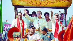
I feel humbled that destiny made me perform a pivotal duty in the form of the Shri Ram Rath Yatra from Somnath to Ayodhya in 1990.
I believe that before any event finally occurs in reality, it takes shape and form in a person’s mind. At that time, I was feeling that a befitting temple for Shri Ram in Ayodhya would indeed be a certainty one day, and that it was only a matter of time. A grand Mandir for Shri Ram at Ramjanmabhoomi had been a desire and mission for the Bharatiya Janata Party. When in the mid-1980s the Ayodhya issue rose to the centre-stage of national politics, I was reminded of the time how political stalwarts like Mahatma Gandhi, Sardar Patel, Rajendra Prasad and K M Munshi had, against all odds, effectively steered the reconstruction of another landmark temple in independent India- the Somnath Temple at Prabhas Patan on the coast of Saurashtra in Gujarat.
Somnath was both a witness to, and a target of, multiple foreign invasions during the medieval period. And reconstructing the Somnath temple was a proud testimony of India’s determination to erase the history of bigoted alien attacks and regain its lost cultural treasure.
Sadly, as in the case of Somnath, the temple at the birthplace of Shri Ram in Ayodhya had also become a target of attack by an invader, Babar, who founded the Mughal empire. In 1528, Babar ordered his commander Mir Baqi to erect a mosque at Ayodhya to make the spot a ‘place for descent of angels’- hence the name Babri Masjid. It is widely believed, and later even confirmed by compelling archeological evidences that there was a pre-existing temple at Ayodhya which was demolished for establishing the mosque.
So in many ways, the Ayodhya movement was the continuation of the spirit of Somnath. When the BJP decided in 1990 that I, as its President, should lead the Shri Ram Rath Yatra to mobilise people’s support for the Ayodhya movement, it took no time for me to choose Somnath as the starting venue of this historic journey.
On 12th September, 1990, I called a press conference at the party office at 11 Ashoka Road, New Delhi and announced my decision to undertake a 10,000-kilometre-long Rath Yatra, starting from Somnath on 25th September and reaching Ayodhya on 30th October to join the kar seva in Ayodhya, planned by the saints associated with the movement. 25th September was special to me as it is Deendayal Upadhyaya ji’s birth anniversary. In my autobiography- “My Country My Life”, I have extensively talked about the Ayodhya Movement and the Shri Ram Rath Yatra that I undertook in 1990. On this momentous occasion today, I would like to recall some significant portions from it. On the morning of 25th September 1990, I offered prayers at the jyotirlingam in Somnath temple. I was accompanied by the present Prime Minister, Shri Narendra Modi (who was then a promising leader of the BJP), Shri Pramod Mahajan, (who was the General Secretary of the party) other senior functionaries of the party in Gujarat, and members of my family. Rajmata Vijayaraje Scindia and Shri Sikander Bakht, both Party Vice-Presidents then, had come to flag off the Rath.
Before the Rath was flagged off, we all paid floral tribute to the imposing statue of Sardar Patel just outside the temple. In my mind, I thanked and drew inspiration from all the great men who had toiled for the reconstruction of the temple. Amidst a large crowd that had gathered to greet and bless us, we climbed the Shri Ram Rath which had been decorated with marigold flowers. Then, to the accompaniment of the sound of the ceremonial conches and full-throated slogans of ‘Jai Shri Ram’ and ‘Saugandh Ram ki khate hain mandir wahin banayenge’ (In the name of Ram, we resolve: We shall build the temple there—at Ramjanmabhoomi—itself), the Rath rolled on. In subsequent days, these slogans became identified with my yatra and a song-“Ram Naam Mein Jaadoo Aisa, Ram Naam Man Bhaaye, Man Ki Ayodhya Tab Tak Sooni, Jab Tak Ram Na Aayein…” sung by late Smt. Lata Mangeshkar, India’s Nightingale, became the signature tune of the Rath Yatra wherever it went.
I was truly overwhelmed by the response to the yatra within the first few days of our journey in Gujarat. The Rath was received by tumultuous crowds everywhere—in villages, towns and even along roads where people from nearby hamlets would gather under trees eagerly waiting for the Rath to arrive. The response reached a crescendo in bigger towns and cities, where it would take hours for us to reach the venue of our meetings.
This response was as big, even bigger, in Maharashtra as well as in all the subsequent states that we travelled through. People everywhere greeted the Rath by erecting ceremonial arches and showering flowers. The most astonishing sight for me was the manner in which people, especially women, would come forward and perform aarti and throw coins, as if they were praying in a temple. What I soon realized, was, that for many people, I was secondary and incidental to the campaign. I was only a sarathi or a charioteer; the principal messenger of the Rath Yatra was the Rath itself. And it was worthy of worship as it was headed for Ayodhya for the sacred mission of construction of the Shri Ram Temple at his birthplace.
At this point, I would like to talk a bit about the ‘Rath’ that I travelled in. It was a actually a mini truck that was redesigned to take the shape of a Rath and was provided with basic amenities.
Travelling in a ‘Rath’ was indeed a novel experience for me, but it presented its own set of challenges. For one, it had a small room-cum–washroom at the rear of the vehicle, which could only be used when the vehicle was not in motion, otherwise it was very bumpy. So I recall standing most times on the platform of the moving vehicle, holding on to the front and side grip bars in order to maintain my balance. Of course, this also meant being constantly subject to heat and dust as the platform was open from three sides.
Also while in motion, it was impossible for me to sip water, juice or tea without spilling. So a special sipper bottle was arranged to overcome this issue. As for food, although arrangements were made that the dinner would come from some party worker’s home in whichever city we were to reach for night halt, invariably the last public meeting would only end up close to midnight. So I would usually have just a glass of milk with marmalade on toast.
Another problem we often faced was due to the height of the Rath. Although the party officials had circulated the information about the height of the vehicle to various destinations along the route of the yatra, as we moved through small towns and cities, one of the frequent hold ups used to be the overhead hanging electrical wires. So party workers then arranged for extra long wooden poles to get the wires out of the way and also started moving along with the Rath. Well, all these were really miniscule issues which form just a small part of the beautiful memory of my Shri Ram Rath Ratra. The most touching moments of the yatra were witnessed in villages and remote hamlets where the piety on the faces of the village folk was of a purer and deeper kind than what I saw in cities. Many of them were either illiterate or nominally educated. They had not learnt about Shri Ram by reading; it was as if the knowledge flowed through them, passed on from one generation to the other, through folk tales or word of mouth, as usually happens in the Indian society.
At many places, I found an odd villager who would come quietly, without shouting any slogans, perform a puja before the Rath, greet me and walk away. I was truly humbled by experiences like these as it gave me a first-hand insight into how deep-rooted religiosity is in the lives of the Indian people. It was the Rath Yatra that made me realise that if I were to communicate the message of nationalism through the religious idiom, I would be able to transmit it more effectively and to a wider audience.
My speeches, delivered mostly from the specially designed raised platform on the vehicle were just about five minutes long, because I had to address nearly twenty to twenty-five such roadside receptions each day. In most towns and cities, I had to get down and address public meetings attended by tens of thousands of people.
I would explain the purpose of the yatra and the circumstances that compelled the BJP to actively participate in the Ramjanmabhoomi movement. Although the people’s response to the Rath Yatra was mainly religious, the focus of my speeches was on nationalism, as I have always believed that the Shri Ram temple issue is intrinsically connected to our sense of Indianness. A recurrent theme in my speeches was that the power of a positive approach to religious faith can contribute greatly to social transformation and nation-building. I stressed on the equal status that our Muslim brethren enjoyed in independent India as India chose to remain non-theocratic and secular. This, I added, was principally due to the age-old secular ethos of Hinduism. I also appealed to leaders of the Muslim community to respect the Hindu sentiments over Ayodhya. My yatra was scheduled to enter Deoria in Uttar Pradesh on 24th October 1990. However, as I had anticipated, it was stopped at Samastipur in Bihar on 23rd October and I was arrested by the Janata Dal government in the state, then headed by Shri Laloo Prasad Yadav. I was taken to an inspection bungalow of the irrigation department at a place called Massanjore near Dumka, on the Bihar-Bengal border. This action invited angry and spontaneous protests all over the country.
LK Advani with Daughter Pratibha and Wife Kamla
This was a time when there were no mobile phones. The news of my arrest reached my daughter Pratibha, who was in Kolkatta then, in quite an interesting manner. She was looking to hire a cab on way back to her home when the taxi driver told her to hurry up. On her enquiring from him why he was saying so, the taxi driver told her that Advani “Baba” had been arrested and people were fearing a backlash in the form of riots in the city! Two days later, Pratibha spoke to Laloo Prasad Yadav ji, who facilitated her coming to meet me at Massanjore during my detention. I spent five weeks in detention before being released.
Thus ended my Shri Ram Rath Yatra, which was indeed an exhilarating episode in my political life. I felt happy that the Yatra helped in galvanising the aspirations, energies and passions of its countless participants.
A significant debate that started during the course of the Ram Janmabhoomi movement was the difference between genuine secularism and pseudo-secularism. On the one hand, there was a groundswell of popular support for the movement. On the other hand, most political parties were shying away from supporting the movement as they feared losing Muslim votes. They succumbed to the lure of this vote-bank politics, and justified it in the name of secularism.
Thus, the Ayodhya issue, whose primary objective was the reconstruction of the Ramjanmabhoomi temple, also became a symbol of reclaiming the true meaning of secularism from the onslaught of pseudo-secularism.
It has been 33 long years since my Shri Ram Rath Yatra. A lot has happened since, including the legal battle which had implicated me and many of my colleagues from the VHP, RSS and the BJP.
However, after almost three decades, on September 30, 2020, the CBI’s special court acquitted me and others and released us from all charges. It is pertinent to note that while on one hand the protracted legal battle was going on, on the other, not only I, but every karyakarta of the BJP and the Sangh Parivar continued working towards awakening the soul of Indians to realise this dream of restoring Ram Lalla at His rightful abode.
I am very happy that due to the decisive verdict of the Supreme Court in November 2019, the reconstruction of Shri Ram Mandir has happened in an environment of tranquility.
And now that the magnificent Shri Ram Temple is in its final stages of completion, I am filled with a sense of deep gratitude towards the present Government headed by Prime Minister Shri Narendra Modi, all organisations, particularly the Vishwa Hindu Parishad, Rashtriya Swayamsevak Sangh, Bharatiya Janata Party, the countless people associated with my yatra, saints, leaders, kar Sevaks and all the people from India and the world, who made valuable contributions and sacrifices in the Ayodhya movement over many decades.
There are two persons who I am missing immensely today. The first one is late Shri Atal Bihari Vajpayee, who had been an integral part of my life- both political and personal, and with whom I shared an unbreakable and everlasting bond of mutual trust, affection and respect.
The second person is my late wife Kamla, who had been the mainstay of stability and a source of unparalleled strength to me, not only during the Shri Ram Rath Yatra, but throughout my long stint in public life.
In the run-up to the upcoming special occasion of 22nd January 2024, the atmosphere in the entire country has truly become ‘Ram-maya’. This is a moment of fulfilment for me, not just as a proud member of the RSS and the BJP, but as a proud citizen of our glorious motherland. My greetings to all my countrymen!
When Prime Minister Shri Narendra Modi does the ‘Pran Pratishtha’ of Shri Ram Lalla’s idol at Ayodhya, he would be representing every citizen of our great Bharat. It is my belief and my hope that this temple will inspire all Indians to imbibe Shri Ram’s virtues. I also pray that our great country not only continues to accelerate on the path of becoming a global power, but also presents itself as a sterling example of dignity and decorum in all walks of life.
I bow at the lotus feet of Shri Ram. May He keep everyone blessed. JAI SHRI RAM!
Watch a documentary on LK Advani’s “Fulfillment of a Divine Dream”
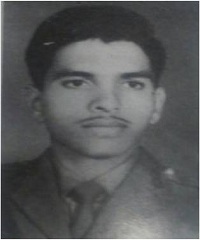
BRAVEHEART Capt Ashok Krishnarao Karkare, Vir Chakra
Penned down By his Elder Brother, Capt. Arun Karkare of Merchant Marine
IC21909 -35LT REGT, Vir Chakra CAPT ASHOK KRISHNARAO KARKARE
This brave heart was born on 30th June 1942 in Wardha, Maharashtra. Ashok was the third child blessed to the parents Krishnarao & Sumati Karkare. As the luck could have it, exactly a year later father Krishnarao joined the then Royal Indian Air Force (RIAF) in search of a better life for himself and the family. Ashok brought new job for his father and a better life for his siblings Sheela and Arun too. Things were on the move for all concerned. The family moved to Delhi as Flight lieutenant Karkare was posted at Air Head Quarters there.
Unfortunately, as child of 2 yrs age Ashok was struck by a rare bone disease then known as “RICKETS”. This bone- softening disease in children is due to failure of the body to maintain adequate level of calcium and phosphorus and this resulted in the hampering of the normal growth of baby Ashok to a point that it was evident that Ashok would not make it to a normal expected height as a youth. There was neither timely quality medical help nor remedy available to Ashok. As the days flew past, Ashok overcame this disadvantage. But the destiny had a different plan in place to use this physical adversity. Ashok excelled in field games such as football, hockey and relay race during his school days in Delhi and London and later in his college in Gurgoan.
Ashok attended School in London as his father was now posted as Assistant Air Attaché at the Indian Embassy in Paris –France. This experience was God sent as he blossomed into a smart young boy. On return to India at the age of 15yrs he continued his education but now a strong attraction to serve in any of the three armed services took charge of his mind. Men in uniform simply fascinated his tender mind with desire to join Army. But his father alerted him about his height disadvantage as it was below the Army standards! Ashok was sad and disappointed indeed.
Now destiny unfolded its plan for him. In 1962 Indo-China war took place. Indian Army needed urgent recruitment of officers. It opened up Officer’s Training School (OTS) at Chennai to train emergency commissioned offices. Ashok applied for it. He was in 2nd year BA-degree course then. He kept it as a well guarded secret. No one got the wind of it at home! He cleared all the prerequisite tests except the final interview followed by medical fitness test. He had to disclose now about his application to join Army to his parents as he prepared to leave for the final rendezvous with his destiny so to say.
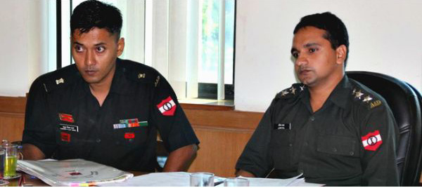
At the interview the miracle happened. A Major General heading the interview team said “Mr Ashok Karkare, Are you not aware of the height requirement for joining Army?”
Representative Image of Army Interview
Ashok was ready with his make or break answer and said
“ I am well aware of it but please note that being short I will be perhaps last one to die in bullet fire from enemy thus holding the ground till the end for my beloved nation !” His words stunned the entire interview board. They clapped and said “we need people like you. You are selected “.
Rest is history. Ashok fought like a lion in 1971 war and proved every word he said in the board room. He brought glory to his nation, family and to himself. JAI HIND.
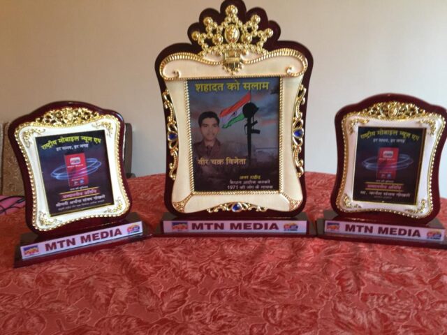
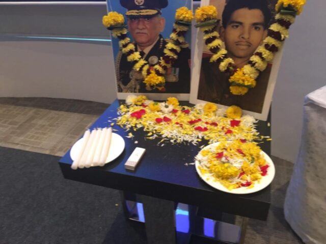
Metro city channel held a special function to honour Capt .Ashok Karkare, VirChakra winner, at Taj Santacruz hotel, Mumbai, with union minister Ramdas Athavle as chief guest. A documentary film has been made on Capt Ashok that was shown on the occassion. Special momentous were given to us too . Ashok and CDS Rawat were in the same frame on the Stage. God is kind indeed. Arun Karkare
Case: 91m High Cavity- Result Of Lacking Geological Study & Support Design?
“Lack Of Investigation may Give Surprise, But Lacking Design Definitely Results In Failure” – Proved Yet Again In Punatsangchhu – II HE Project
– The Case History of Massive Crown Failure In The Huge Cavern. A Perspective Explained Citing Facts, Figures, Analysis & International Technical Literature Of Renowned Authors
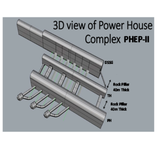
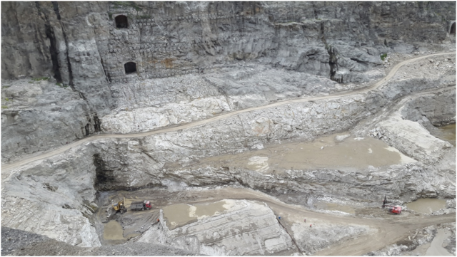
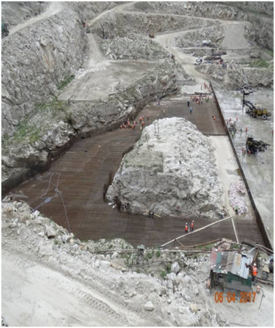
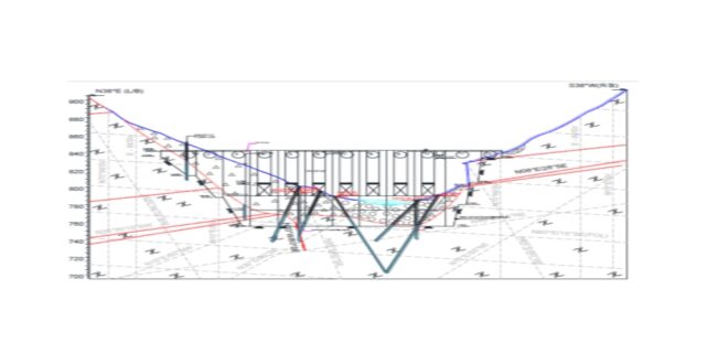
A huge cavity of the size of a football field and a height of one third of the height of Eiffel Tower formed through the crown of the 314m(L)x 19m(W) x 58.5m(D) underground cavern of the Downstream Surge Gallery (DSG) of Punatsangchhu-II H.E. Project (1020MW) in Bhutan (PHEP-II), at the time when the cavern was under excavation for 3 years and had been yet excavated to a depth of 35m to 40m. The failed reach of the DSG, assessed originally as ‘fair to good rock mass’, is actually comprising highly jointed and fractured rock-mass of class IV & class-V and acted as the hanging wall formed by the major shear zone with 55ᵒ dip and containing a number of smaller shear zones, which intercepts the DSG and its two adjacent caverns of the PH Complex, throughout their depth. This Shear zone remained unexplored in the original geological assessment.
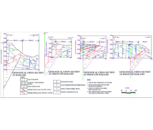
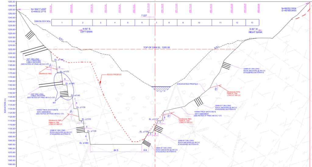
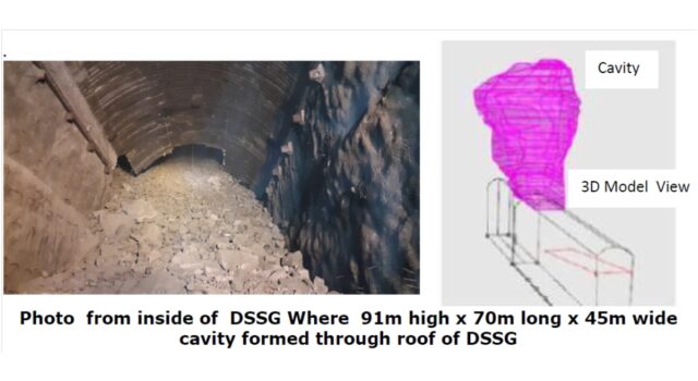
The Punatsangchhu-II (PHEP-II), a 1020 MW project with scheduled date of commissioning of year 2017 at cost of Rs. 37778 millions, new approved project cost of Rs. 72900 millions ( US $ 1.04 billions), expects further escalation in its cost to Rs. 80000 millions ( US $ 1.14 billions), with already incurred cost of about Rs. 65880 millions, is delayed due to the huge rock mass failure in its underground Downstream Surge Gallery (DSG), resulting in a huge cavity of about 91m height x 70m length and 45m width in the crown of the DSG. The Dam foundations had encountered, a thus far unexplored,mega shear of maximum 30m width, cutting across the length all the 4 dam blocks diagonally. The shear zone with its about 35ᵒ to 45ᵒ dip, continued under the foundations to large depths.
There is a strange coincidence of massive geological surprises and huge rock mass failures, which happened in the two mega hydroelectric projects named Punatsangchhu -I & II H E Projects, under construction since 2009 -10 in Bhutan.
Occurrence of too many geological surprises, the apparent cause of the big mishaps in the two mega Projects, in fact may be a case of ‘ harping on the geological surprises’ as a scapegoat for the lack of proper geological investigations carried out by the Main Consultants for geological assessment to be done by their retained Geology Consultants and inappropriate designs carried out by their retained Designer Consultants.
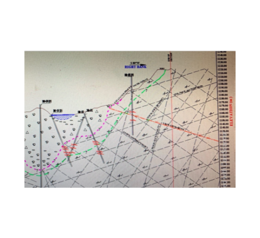
1. CHANGE FROM A SURFACE POWER HOUSE TO UNDERGROUND POWER HOUSE
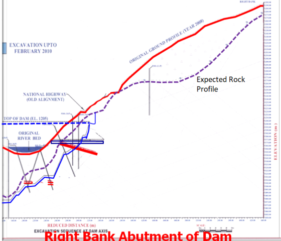
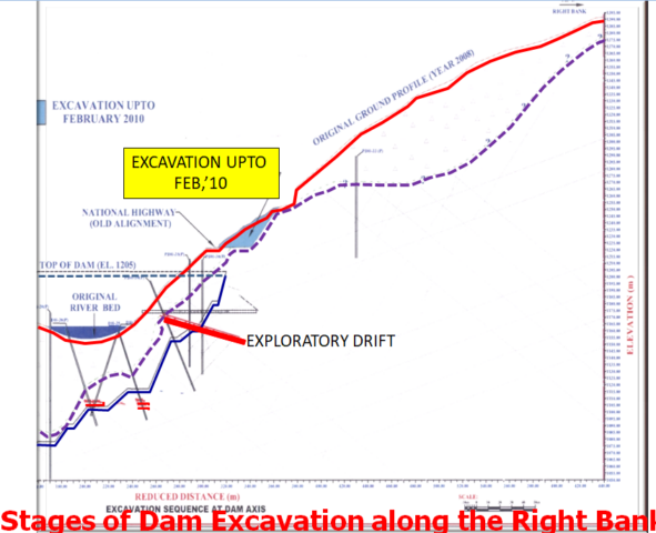
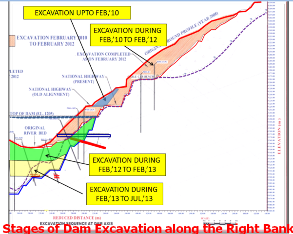
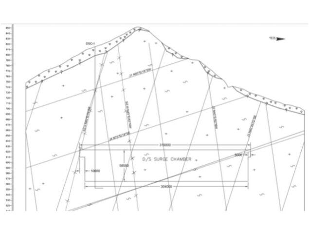
Originally in the DPR, the Power House Complex was contemplated to be a Surface Power House, to be located on the right bank at a site 3km downstream from the present location of the Underground PH Complex. The change of PH Complex to underground site selected by the Consultants was based on limited exploration apparently through one borehole DSC1 only as reportedly the additional borehole DSC3 was driven by the Consultants at a different far away location to that was suggested by their own Geology Consultants and the same did not even penetrate through level of crown of DSG and ended much above it besides that the hole was not properly located.
The change of location of the PH Complex to the underground site was made just before the start of construction in 2010. The significant observation by the Geology Consultant, in their geotechnical assessment were stated that, “Rock mass conditions of only limited reach in the DSG have been explored”.
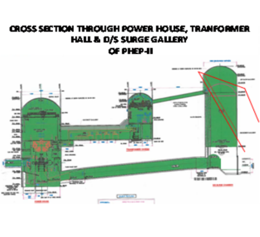
Fig. – 1
2. GEOLOGICAL ASSESSMENT OF THE UNDERGROUND SITE OF PH-COMPLEX WAS BASED ON AN INADEQUATE GEOLOGICAL INVESTIGATIONS DONE BY THE CONSULTANTS
The location of the additional bore hole DSC3 for the DSG, suggested by the Geology Consultant and drilled during investigation of the site by the Main Consultants, was drilled at a wrong location. The Geology Consultant had in-fact reported that the location of the inclined exploratory holeDSC3, drilled above DSG for geological investigations was not the same as what it had advised to and required from the Consultants.
Thus the rock mass in the DSG crown was not explored at the particular specific location suggested by the Geology Consultant. Also therefore the rock mass comprising the 58m high walls of the DSG too remained to quite an extant unexplored at the location desired by the Geology Consultant.
The Geology Consultant in-fact had reported, in 2010, on the geo-technical investigations done by the Consultants , that less information about the DSG is available for the selected location of power house complex of Punatsangchhu-II H.E.P.
The Geology Consultant’s report stated, “PH Complex is intruded by a number of pegmatite and leucogranite veins/bodies. Five joint sets are prominent which are open to tight in nature, filled with clay and rock flour. The rock in the major reach of PH, TH and DSG cavern is inferred to be FAIR TO GOODrock as per Q system. Shear/highly fractured zones may be encountered in the Downstream Surge Gallery cavern”.IT further strongly recommended to ” MINIMIZE THE SIZE OF SURGE CHAMBER AS FAR AS POSSIBLE“.
* Therefore as a result, the location of the underground DSG was fixed by the Consultants, based on a geological assessment drawn from a very limited exploration. The geological assessment, later during the excavation, was actually found to be a grossly wrong .
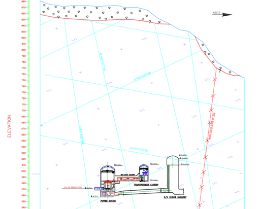
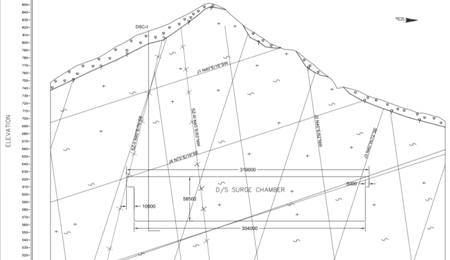
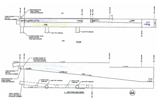
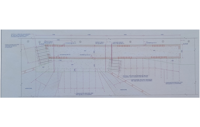
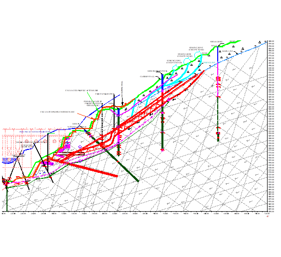
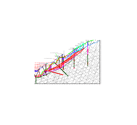
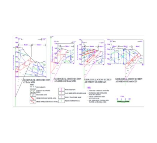
Tender Drawing of Geological Section Through PH Complex
Tender Drawing of Geological Section Through DSG – Showing the only sole Bore Hole DSC1 being the basis of geological Assessment
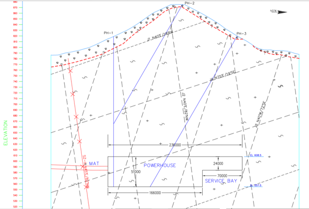
Tender Drawing of Geological Section Through PH Cavern Showing Bore Holes PH-1, PH-2, and PH-3
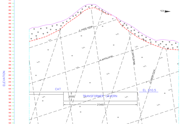
Tender Drawing of Geological Section Through TH Cavern
Fig. – 2
It may be seen that Tender Specification Geological Drawings Show No Presence of Mega Shear Zone,Which Was Later Encountered During Excavationand was found cutting across the three caverns through out their full depths.
3. PROGRESS OF EXCAVATION IN PH-COMPLEX BY FEBRUARY 2016
The underground powerhouse complex comprises three large caverns viz. Power House (241m x 23.9m x 51m), Transformer Hall (216m x 14m x 26.5m) and Downstream Surge Gallery (314m x 19.8m x 58.50m) on the right bank of Punatsangchhu River. Excavation of Transformer Hall cavern had been completed to its final depth at EL ±582m, whereas, in Power House/ Machine Hall cavern it was about to completed. The foundation of Turbine Pit -1 with its bottom at EL ±555.84m had already been achieved and rock covering had been done in the Pit. Prior to collapse, excavation of the Down Stream Surge Gallery (DSSG) had reached maximum up to EL ±578m in reaches beyond RD ±210m and in rest of the reaches it was at EL ±593m, including in the failed zone. The DSSG is aligned at N10ᵒE direction for which excavation started in the month of April 2013 by executing its central gullet at its crown at EL ±623.70m, followed by widening of the crown which completed in the month of August 2014.
Initially the proposed length of the DSSG was 210m. Later on, it was extended up to 314m. In the first phase it was excavated from RD 0m to RD 210m with its crown at EL ±623.70m and in the second phase benching was carried out from RD 0m to RD ±210m from springing EL ±615m. The excavation of heading of remaining length of the DSSG, from RD ±210m to RD ±314m, with its crown at EL ±613.70m, was carried out simultaneously.
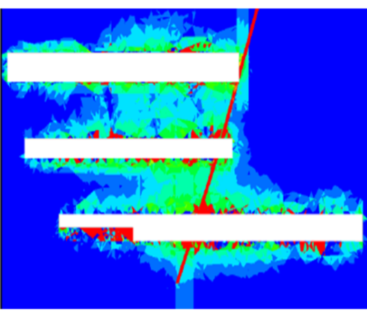
Progress of Excavation In PH-Complex By February 2016 Shown In Green Color Fig. – 3
Progress Of Excavation in Downstream Surge Gallery By February 2016 Fig. – 4
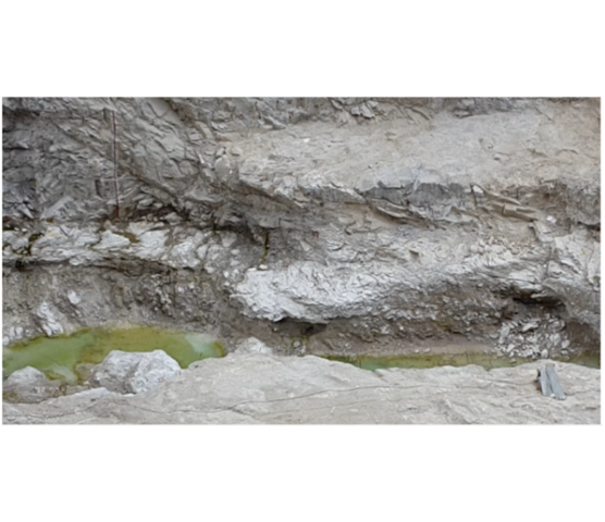
4. ACTUAL GEOLOGY ENCOUNTERED
The rock mass encountered in the DSG comprises quartzo-feldspathic gneiss, biotite micaceous quartzite with leucogranite and pegmatite patches and veins. Generally due to intrusive nature pegmatite occurs in the form of veins along joints, whereas leucogranite is present in the shape of patches/bands across or along parent rocks. At places leucogranite/pegmatite is crushed / sheared and fractured due to deformation/folded rock strata. In general foliation has gentle dips 10ᵒ-25ᵒ / N205ᵒ-240ᵒ direction and variation in the attitude of foliation is mainly attributed to warping and minor folding. The rock mass encountered in the central gullet falls in class III (40.00%), class IV (50.95%) and class V (9.04%). The class V (Q= 0.19 – 0.58) rock mass mainly occurs in the major shear zone and its vicinity. Major geotechnical problems which were encountered, were occurrence of major shear zone (45ᵒ-60/N030ᵒ) and formation of cavity in the crown during excavation central gullet (RD ±121 to RD ±129m), low dipping foliation joints posing slabbing conditions in the crown portion, erratically occurrence of intrusive bodies of variable dimensions, minor shearing along foliation joints and other joints at few locations. Besides presence of water (seepage/dripping) along shear zone and ingress of water on the right wall between RD 308m and RD ±313.5 (EL ±599m) were main problems.
ROCK MASS CATEGORY ACTUALLY ENCOUNTERED IN THREE CAVERNS :
CAVERN
FAIR TO GOOD
POOR TO FAIR
POOR
VERY POOR
PH CAVERN
NIL
44.8%
54.07%
1.12%
TH CAVERN
NIL
35.65%
56.94%
7.4%
DSG CAVERN
NIL
40.0%
50.95%
9.05%
The rock type actually encountered was ‘very poor to poor and poor to fair’ instead of ‘fair to good’. The same is also confirmed by Norwegian Geotechnical Institute (NGI).
Geology Consultant’s Assessment Report missed the Shear Zoneencountered in central gullet of DSG from RD ±121m onwards dipping 45ᵒ -60ᵒ due N30ᵒ-35ᵒE having thickness ~1.5m-3.5m. The Q value in shear zone reach, from RD ±121m to RD 135m, has been 0.2-0.58 (Class-V).
Actually DSG encountered 14 nos. of Shear Zonesof size 2cm to 3.5m in contrast to only 2 nos. assessed of size 2cm to 60cm.
5 nos. of Major Joint Sets including Foliation joint with low dip & direction 10ᵒ-15ᵒ : SW to NW, spacing 0.02 t0 0.3m. Joints, adversely oriented for wedge actions have continuity 10m to 15m are generally altered and stained and showing warping.
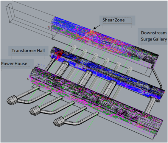
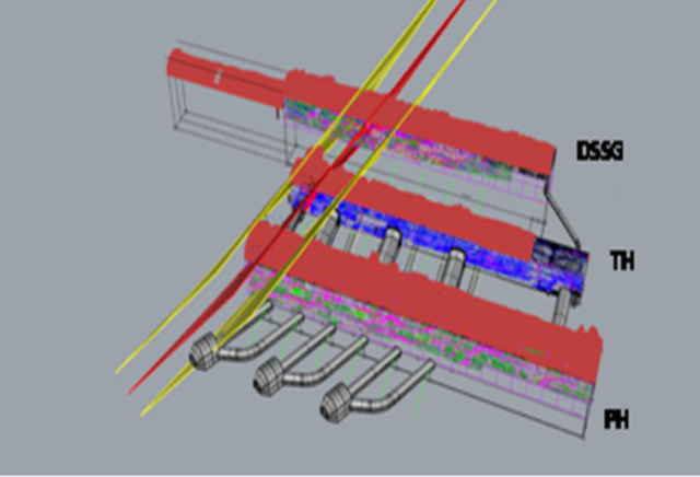
Actual Geological Setup in PH Complex Fig. – 53D View of Shear Zone Intersecting DSG, TH & PH Caverns Fig. – 6
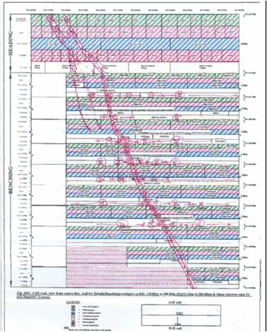
Shear Zone Intercept in DSG U/S Wall From RD 130m to RD 180m
Shear Zone Intercept in DSG D/S Wall From RD 130m to RD 180m
Fig. – 7
The major shear zone (45ᵒ-60ᵒ/N030ᵒ) encountered at the crown portion between RD ±121m and RD ±140m and extending on the either wall dipping towards face (gable end wall) is shown above.
The hanging-wall portion of the DSG, in its in-situ conditions is propped up by the major shear zone. The Shear Zone reach, from RD 121m to RD 140m, is formed of the rock mass of class- V and the hanging-wall reach beyond RD 140m to RD155m comprise Class-IV, having predominantly Leucogranite with micacious quartzite, biotite gness & pegmatite veins/ bands. Rock mass in this reach is highly jointed and fractured having joints of 10mm to 20mm opening which are filled with clay / crushed material.
5. OVER EXCAVATIONS DURING EXCAVATION OF THE CENTRAL GULLETS IN THREE CAVERNS
Water seepage in the shear zone which further lowered the shear parameters resulted in cavity formation of ~2-7m height in the central gullet of DSG with range of cavity of about 1.55m~ 3.05m at RD 117.0m to 7.87m~7.96m at RD 125.0m to 1.5m~3.5m at RD 138m . Rib supports in the central gullet in the shear affected reach have been provided along with rock bolts of 8m/10m long followed by, additional rock bolts of 12m length provided after installation of rib supports and their back filling and grouting for the full section, as per Designs. Over breaks in these reaches during widening of the Central Gullet remained of the order of 1.0m to 3.0m 0nly.
However, the range of maximum over break in the DSG from RD 138m onwards was of the order of height of only 1.5m to 3.5. This reach from RD 140m to RD 210m is the reach where, later after three years, the huge rock fall has occurred.Incidentally the location of the 8m cavity ,which happened earlier in April 2013, between RD 117m to RD 125m in the DSG, when Shear Zone was exposed in the Central Gullet of the DSG, has remained intact and unaffected from the huge rock fall that happened on 03 March 2016.
The reach of the DSG from RD 140m to RD 210m , which suffered massive rock fall, had witnessed only 1.5 m to 3.5m of over excavation that too only during the excavation of the Central Gullet, as compared to the locations which are intact despite suffering much higher order of over excavations of 8m to 14m in PH and TH caverns and even RD 124m in the DSG itself.
In TH, from RD 84.5m to 95m and then from RD 144.5m to RD 164m, the over excavation ranged from 0m to 5.7m. It ranged from 0m to 5.7m, from RD 175m to 183m and the over excavation in TH it ranged from 0.24m to Max. 7.5m and from RD 190.5m to 207m it ranged from 0m to 13.95m
In PH from RD 116m to 126.5m the over excavation ranged from 0.8m to 3.5m, from RD 137m to 142.5m ranged from 0m to 4.2m , from RD 150m to 159.5m ranged from 0m to 8.2m and from RD 171m to 175m ranged from 0m to 3.8m.
Thus TH and PH caverns experienced much larger sized over excavations i.e. of the order of height of 8m to 14m as compared to the almost entire reach in DSG where the over-excavations remained limited to the order of height of only 1.5m to 3.5m.Both TH and PH through out their entire lengths including locations of as high over excavation as 8m to 14m , with multiple large openings in their walls, are intact .
The only different feature being that the DSG is intersected by the Mega Shear Zone in its crown and also it cuts through entire 58m depth of its walls. The Toe of the Shear Zone got removed during excavation of DSG. Whereas both in the TH and PH Caverns , the Shear Zone is confined and embedded in the Gable End. It does not pose danger in the PH & TH caverns of removal of toe of the Shear Zone there, like the way DSG witnessed it.
The incidents of over excavation have occurred due to extensive presence of pegmatite veins/ bands and low dipping Foliation joint with dip & direction 10ᵒ-15ᵒ . Excavation in many continuous reaches had not required blasting or was applied with least charge of 0.19 to 0.55 kg/m3. Rock fall due to slabbing action were happening repeatedly .
Incidents of over excavations get explained by the International Research :
* INTERNATIONAL LITERATURE WARNS THAT THE STRUCTURALLY WEAK GEOLOGY IS PRONE TOUNAVOIDABLEOVER EXCAVATIONS
Reference : Forty Years with The Q-System in Norway and Abroad by Nick Barton Eyestein Grimstad :-
“In underground excavations if the ratio of JN/JR ≥ 6 is encountered ,over breaks are extremely likely to occur despite contractor’s best efforts with careful blasting.”
In PHEP-II PH Complex caverns the Jn/Jr = 9 to 12
This explains tendency of over excavations despite use of controlled blasting using charge factor of only 0.6 to 0.8 kg/m3 & even when at many locations merely scooping was used for tunnelling in central gullet.
The presence of numerous and adversely oriented clay filled joint sets in combination with sub-horizontal foliations and rock mass intervened by pegmatite was bound to result in uncontrolled over breaks.
6. DESIGNED ROCK SUPPORT MEASURES
Rib supports in the central gullet which were extended to full section after side slashing, were provided in the entire reach of all the three caverns of PH, TH & DSG. The rock support measures thus provided as per construction drawings comprise SFRS 200mm thick, 8m/10m long rockbolts and ISMB350 steel ribs @ 0.5m spacing with backfilling of concrete and grouting in the crown for the full section, as per the Designs .
The selected reaches of over excavation were provided by additional rock bolts of 32mm dia and 12m length as advised by the Designers.
The shear zone and its associated zone reaches, in the DSG walls, where it has been exposed, was treated providing concrete cladding, 12m long rock bolts and grouting as per the construction drawing.
However whether this designed treatment was sufficient to strengthen the rock pillars , provided of just 40m thickness, between multiple caverns situated adjacently and moreover when the pillar is intersected critically throughout its depth and thickness by a mega Shear Zone . The intercept of the Pillar by Shear Zone would have made it a cracked pillar. This Question was best to be answered if and only if a scientific 3D Numerical Analysis of the underground PH Complex would have been done by the Designers incorporating actual geology. However, apparently the analysis was not done by the Designers at that stage.
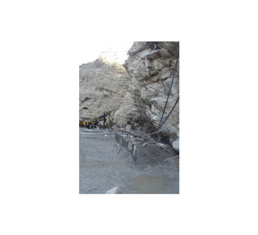
7. SINKING OF RIBS OBSERVED IN NOVEMBER 2014
During widening of DSG from RD 117.5 m to RD 132m, rock bolts could not be installed immediately after excavation, as the holes were getting collapsed during drilling. hence in order to mobilize immediate rock support, support system of 200mm thick SFRS and Built-up section as per construction drawings were provided and backfilled in this reach. Side slashing /widening of Machine Hall, Transformer Hall and & DSG had been done by adopting controlled blasting and charging technique i. e line drilling, alternate charging of periphery holes. The charge factor observed at site ranged from 0.6 to 0.8 kg/m3 which was considerably low. The rock bolts/wedges had got detached during widening thereby affecting the crown profile and arching action of roof caverns. At some locations in Class III reach of central gullet of these caverns, rock bolts got exposed after loose fall during side slashing. As reported, the geological features are uncertain and of intrusive nature with pegmatite veins, leading to frequent rock fall and accident to men and machinery.
In view of all the above and considering permanent stability of these caverns, it was requested to Consultants a number of times, in fact 29 times between May 2013 to dated 23.12.2013 to suggest adequate supports at the crown of all these caverns before start of excavation in Benching .
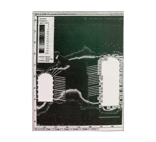
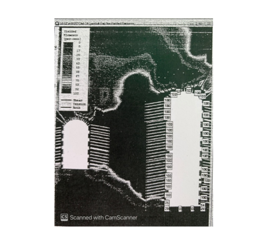
During November, 2014, at El. 618.08m, a gap of 55mm had been between ribs and cladding on the D/S wall of DSSC at RD 130m to RD 170m at the location of shear zone and that of 20mm on the U/s wall at RD 170m to RD 180m. The surface target installed on D/s wall showed a sinking of 20mm at springing level. The reaches were cement grouted as advised by the Designers / Consultants after observing no further increase in distress.
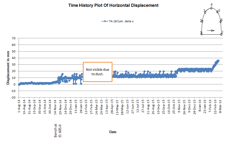
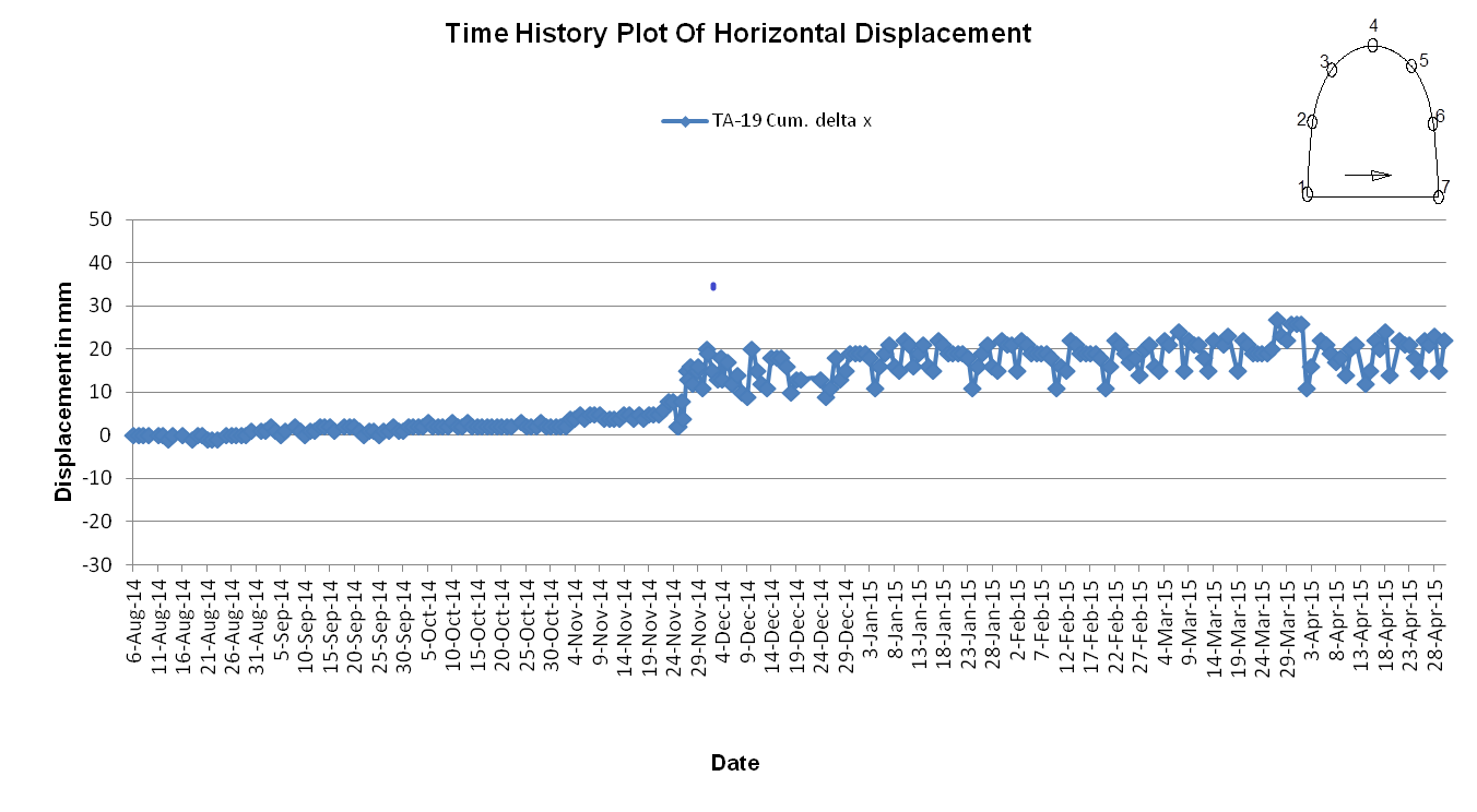
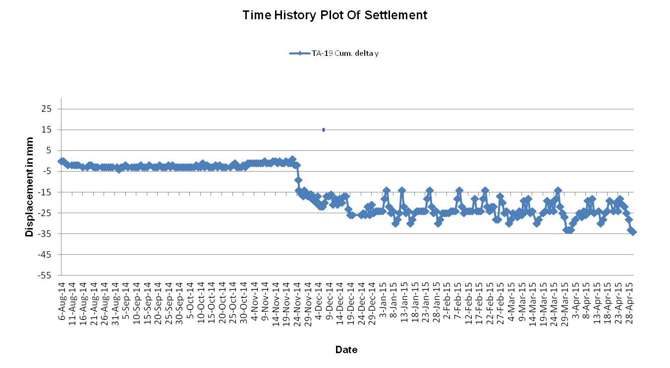
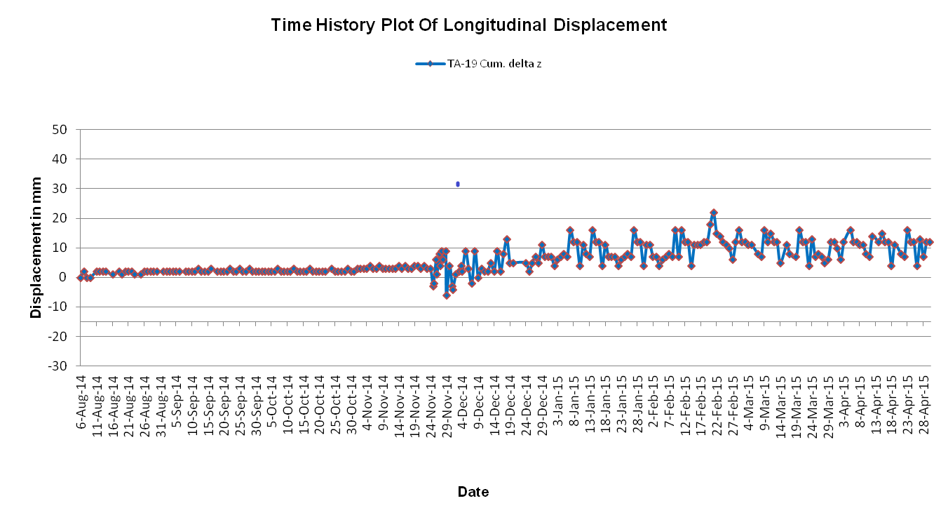
Time History Plot Of Displacements Of Crown At RD 135m :
Plot of X- Displacements
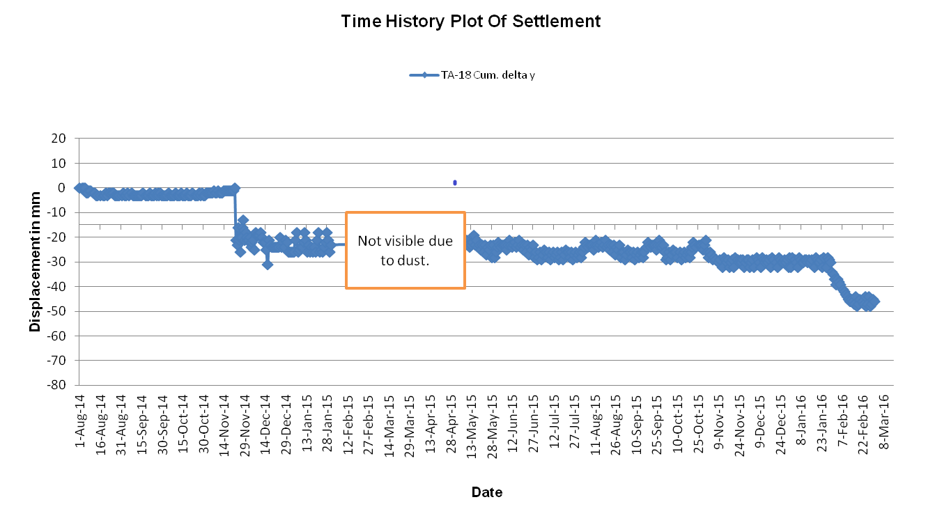
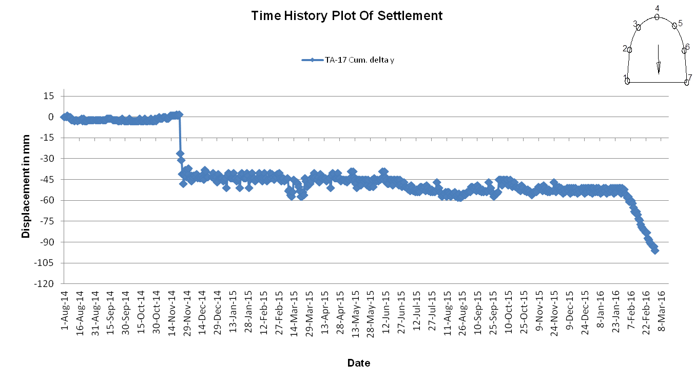
Plot of Y- Displacements
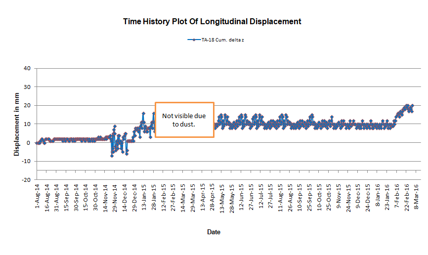
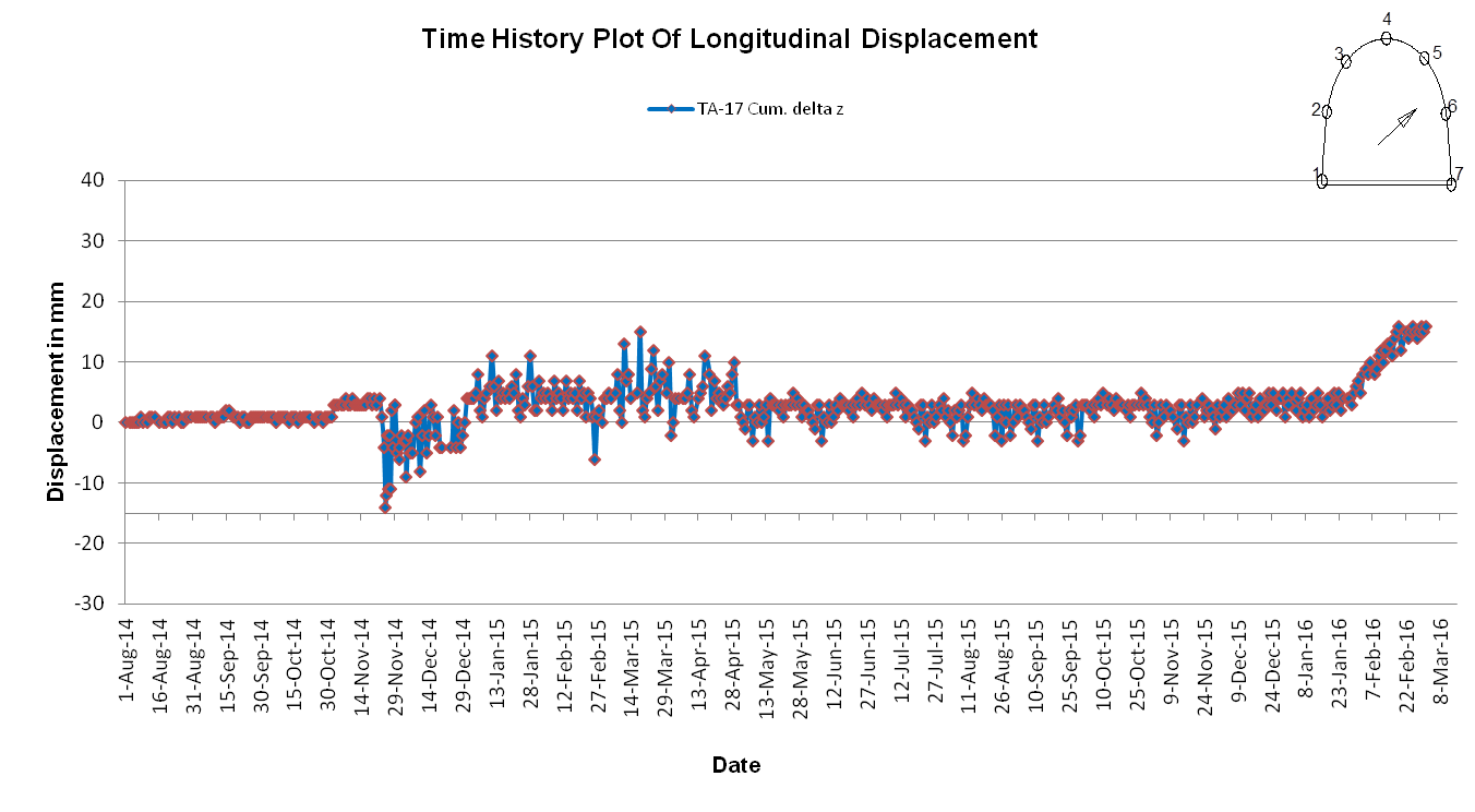
Plot of Z- Displacements
Significant Displacements observed around 29 November 2014, 09 November 2015 and 03 March 2016
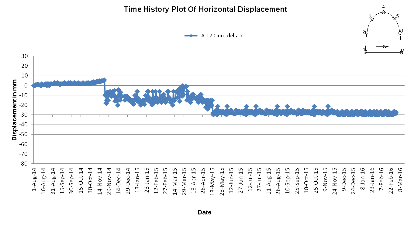
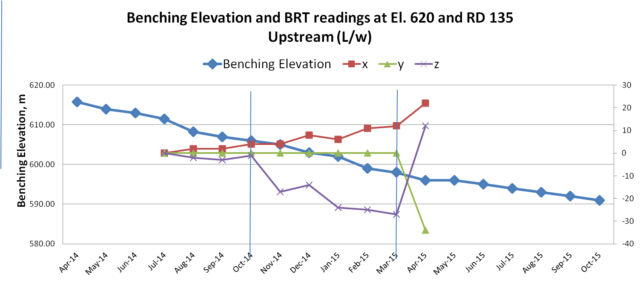
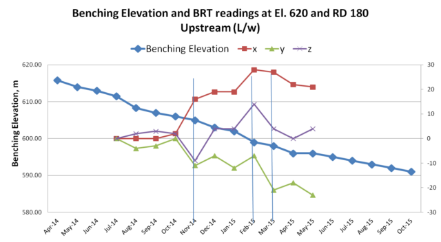
Time History Plot Of Displacements At El. 620m in Upstream Wall At RD 135m
Plot of X- Displacements
Plot of Y- Displacements
Significant Displacements observed around 29 November 2014 followed by frequent fluctuations in displacement trend but amounting to increase in displacement
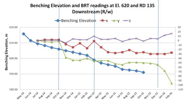
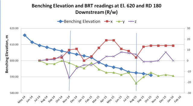
Time History Plot Of Displacements At El. 620m in Downstream Wall At RD 135m
Plot of X- Displacements
Plot of Y- Displacements
Plot of Z- Displacements
Significant Displacements observed around 29 November 2014 followed by frequent fluctuations in the displacement trend and thereafter again sudden displacements are observed from 07 to 22 Feb 2016
It may be observed from the Time History Plots of Displacements at Crown Level and El. 620m in both Upstream and Downstream Walls of the DSG at RD 135m ( shown above) that a sudden displacement in all the three directions were first noticed on 29 November 2014 in the BRT Surface Target Installed (Location of Target in Crown Shown as Yellow colored in Fig. – 8 below). The displacement kept increasing with sudden sharp increments along progress in Benching.
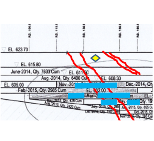
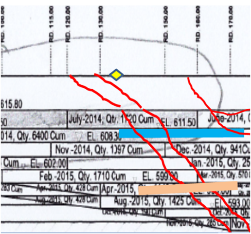
However, around November 2014 , the location of progress of the excavation in Benching in the reach surrounding RD 135m coincided with the location of occurrence of Shear Zone at the level of Springing of the Rib Arches supporting the crown of the DSG Cavern (Refer Fig. -8 below).
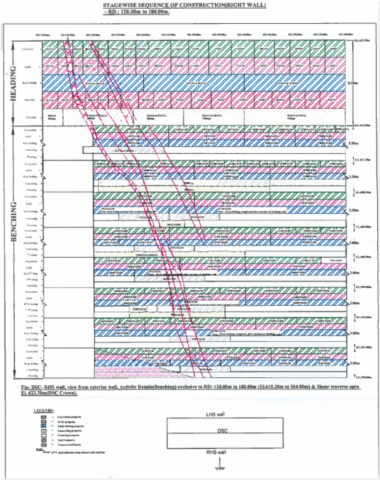
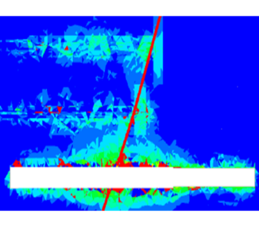
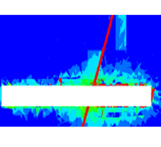
Benching Excavation In Shear Zone Intercept Reach – D/S Wall of DSG – During Around November 2014
Benching Excavation In Shear Zone Intercept Reach – U/S Wall of DSG – During Around November 2014
Fig. – 8
8. MAJOR MISTAKES COMMITTED OF NOT TAKING APPROPRIATE MID-COURSE CORRECTIONS IN THE LAYOUT & SUPPORT DESIGNS, RIGHT AT THE STAGE OF START OF BENCHING EXCAVATION, DESPITE BEEN SUGGESTED THE CORRECTIVE MEASURES, AS EXPLAINED BELOW
8.1 The Suggestion Given By The Geology Consultants To Keep Size Of DSG Cavern Smaller By Adopting A Network Of Tunnels And Galleries Of Smaller Size, Was Not Adhered To :
The Geology Consultants had categorically advised to the Main Consultants and the Designers in their 2010 report that, “The Shear/highly fractured zones may be encountered in the Downstream Surge Gallery cavern”and therefore MINIMIZE THE SIZE OF SURGE CHAMBER AS FAR AS POSSIBLE“.
* INTERNATIONAL LITERATURE WARNS THAT POOR GEOLOGY WITH ROCK MASS RATING BELOW 50, IS NOT SUITABLE FOR LARGE CAVERNS
Reference : UNDERGROUND EXCAVATIONS IN ROCK by HOEK & BROWN (Page 299):-
“The stability of the rock in immediate vicinity of the underground openings in deeper excavations depends upon behavior of the entire rock mass surrounding these openings.
This rock mass may be so heavily jointed that it will tend to behave like an assemblage of tightly interlocking angular particles with no significant strength under unconfined conditions.
Therefore Large caverns should only be excavated in rock with adjusted total classification ratings of 50 or better “
* The RQD rating for the DSG stands evaluated of the order of 40 only, which is not favorable for excavation of caverns with larger sized depth. Geological Consultant had also cautioned in their investigation report to not provide large sized DSG.
However, the Designers / Consultants had provided 314m long x 19.5m wide x 58.5m high single large cavern of the Downstream Surge Gallery (DSG) against the advice of the Geology Consultants.
The Designers should have reviewed the size of the DSG after the Shear Zone was detected to be intersecting the DSG in its entire depth and relocation of the DSG was not seen possible by them. However the Designers ignored a request made by the Project Management to adopt a set of smaller chambers which shall be interconnected by a network of tunnels. After the rock fall in the DSG, it has become necessary and is being done so to redesign the DSG layout comprising additional smaller chambers and tunnels which make up for the lost volume of the abandoned reach of the DSG.
8.2 Results Of Numerical Analysis Informed To The Consultants Indicating Potential Extensive Yielding In DSG Walls In Shear Zone Affected Reach Was Ignored :
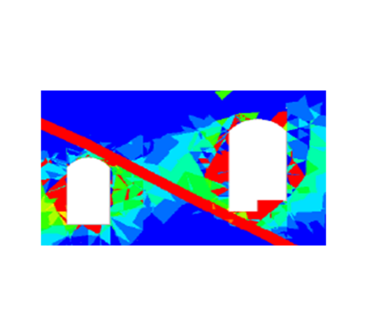
After, the gap of 55mm that occurred between ribs and cladding on the D/S wall of DSSC at RD 130m to RD 170m at the location of shear zone and the gap of 20mm on the U/s wall at RD 170m to RD 180m, in the DSG at El. 618.08m along with sinking of the ribs by 20mm at springing level in the November, 2014, the Contracting Agency responsible for construction of the Power House Complex had carried out a Numerical Model Analysis of the DSG cavern. The analysis established that when the DSG excavation reaches 2/3rd of its depth, there would be wide spread yielding of rock mass occurring in the walls of the DSG. It established that with further progress of the excavation to its full depth of 58.5m, the yielding of rock mass would be 100%.
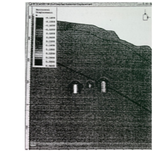
Yielded Zone of Rock Mass in The Rock Pillar When DSG is Excavated to 2/3rd of its Height
Yielded Rock Mass in The Rock Pillar When DSG is Excavted to its Full Height
Fig. – 9
The results of the analysis were informed to the Designers Consultants , but they did not agree with the findings of the analysis performed by the Contracting Agency and ignored the same.
8.3 The Suggestion To Provide Wall Beam Over The Shear Zone And Providing Of Cable Anchors Was Not Adhered To:
Based on the findings and results of the above mentioned Numerical Analysis, it was suggested by the Project Management to the Designers to provide Wall Beam at El. 608m. It was also suggested to the Designers to design appropriate Cable Anchors to strengthen the crown and walls of the DSG in the reach affected by the Shear Zone.
However the provision of Wall Beams and Cable Anchors was not agreed to by the Designers.
8.4 The Layout Design Of The Three Caverns Which Needed To Be Changed To Provide Thicker Rock Pillars Between The Adjacent caverns Was Not Done :
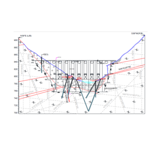
PHEP-I is the nearest located H E Project at 11Km in the U/S of PHEP-II and both have almost identical layout. Incidentally, both PHEP-I and PHEP-II have been contemporary in their designs and construction by the same Designers and Consultants.
As the rock mass in PHEP-II underground DSG has been Class –IV (poorer, which is further weakened due to its intersection by major Shear Zone at 55ᵒ dip, in comparison to that of Class – III (better rock class) in PHEP- I, therefore the Pillar/ wall width in case DSG of PHEP-II, logically, should have been kept larger than pillar width provided in PHEP-I of 40m ( refer Fig. – 1 given earlier above).
Further, In case of PHEP-I, the thickness of rock pillar / wall between PH and TH cavern is 52.5m , which is equal to depth of the PH cavern there in PHEP-I. On that lines thickness of the rock pillar / wall between TH and DSG of PHEP-II, logically, should have been 58m i.e. equal to the depth of DSG , instead of the presently provided thickness of 40m.
* The principal of providing thickness of the rock pillar equal to the depth of the cavern with larger depth of the adjacent two caverns is recommended also by the following International research :
* Reference : Design of large underground caverns – paper by Cheng Y and Liu , Taiwan, – 6th Cong. ISRM, Montreal :
” The pillar width between two caverns should be equal to or more than the depth of thecavern with larger depth of the two”.
Out of the adjacent caverns of DSG and TH , the DSG is of larger depth that of 58.5m. Thus the rock pillar between TH and DSG should have been at least 58.5m thick. In fact because a major shear zone is intersecting this pillar, the thickness of the rock pillar provided should have been still bigger than 58.5m was
However the 40m thickness of the DSG Pillar was fixed or designed, if at all on the basis of some design, it must have been done so, prior to coming to know of both the actual poor geology and the intersecting shear zone. Therefore 40m thickness of the pillar being already lacking the thickness as stipulated by International Researches, had in fact become further weak due to its intersection by the Shear Zone.
This stand gets vindicated by the results of the 3D Numerical Model Analysis done by an independent agency of repute, to study behavior of the original designed layout of the three caverns under actual geological conditions and without incorporating any over excavations (Refer Paragraph No. 12 below). The analysis, which had not included any effect of over excavations accounted for, yet establishes that, the DSG walls, along the intercept made by the shear plane, in fact had already yielded up to 10m to 15m depth in the 40m thick rock pillars at haunch level of the crown and below, over a large length of the DSG walls, in the reach RD 140m to RD 210m , in the hanging wall side of the shear zone where throughout this reach the shear zone intersected the rock pillars/ walls of DSG.
It is certain that if a scientific analysis was ever done originally by the Designers to fix the layout and thickness of the pillars / walls kept between the adjacent caverns of the underground PH Complex, the safety and stability of the DSG cavern with the provided thickness of rock pillars, under actual poorer geological conditions and the presence of the intersecting Shear Zone, would have been seen to be failing with progress of excavation in benching.
9. PLOTS OF DISPLACEMENTS AT RD 135m & RD 180m SHOW THAT THE DISPLACEMENTS WERE INCREASING WITH PROGRESS OF BENCHING
Plot of Displacement in the Upstream Wall At El. 620m in the Crown Arch of DSG at RD 135m
Plot of Displacement in the Downstream Wall At El. 620m in the Crown Arch of DSG at RD 135m
Plot of Displacement in the Upstream Wall At El. 620m in the Crown Arch of DSG at RD 180m
Plot of Displacement in the Downstream Wall At El. 620m in the Crown Arch of DSG at RD 180m
Figs. – 10
It may be observed from the above Plots of Displacements at RD 135m and RD 180m, that the displacements were increasing with the progress of excavation in Benching, despite the walls having been supported with the designed rock support system.
The rock mass in the wall, beside been intersected by major Shear Zone dipping 45ᵒ -60ᵒ due N30ᵒ-35ᵒE having thickness ~1.5m-3.5m, comprise Quartzo feldsphatic biotite gneiss / biotite gneiss/ micaceous quartzite with leucogranite & pegmatite, minor shear seams , thinly foliated rockmass with low dip[ping foliation (10ᵒ – 25ᵒ / N200ᵒ – 230ᵒ) joint at places.
The general rock support system provided in the walls, as per drawings, comprise 8 – 10m long rock bolt ( 36 mm dia.) @ 1m/ 1.5m C/C & SFRS 200mm thick.
The reach in walls in Shear zone and associated weak rock mass has been supported with concrete cladding and two sets of 15m long 36mm dia rock bolts followed by consolidation grouting. Out of the two sets of rockbolts provided for cross stitching the shear zone, one set of rockbolts driven from South to North direction were ending entire part of their anchorage length in the shear zone/ class IV fractured rock mass. Wire mesh with consolidation grouting has been provided in the vicinity areas of shear zone having fractured / crushed rock mass. At places minor seepage has been observed along shear zone and its vicinity.
10. THE OBSERVATIONS OF INSTRUMENTATION IN DSG
With the Benching progressing deeper, the reach in the Hanging Wall comprising fractured rock mass suffered subsidence and drifting with increased dilation due to increased depth of excavation.
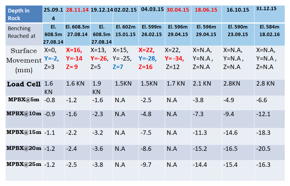
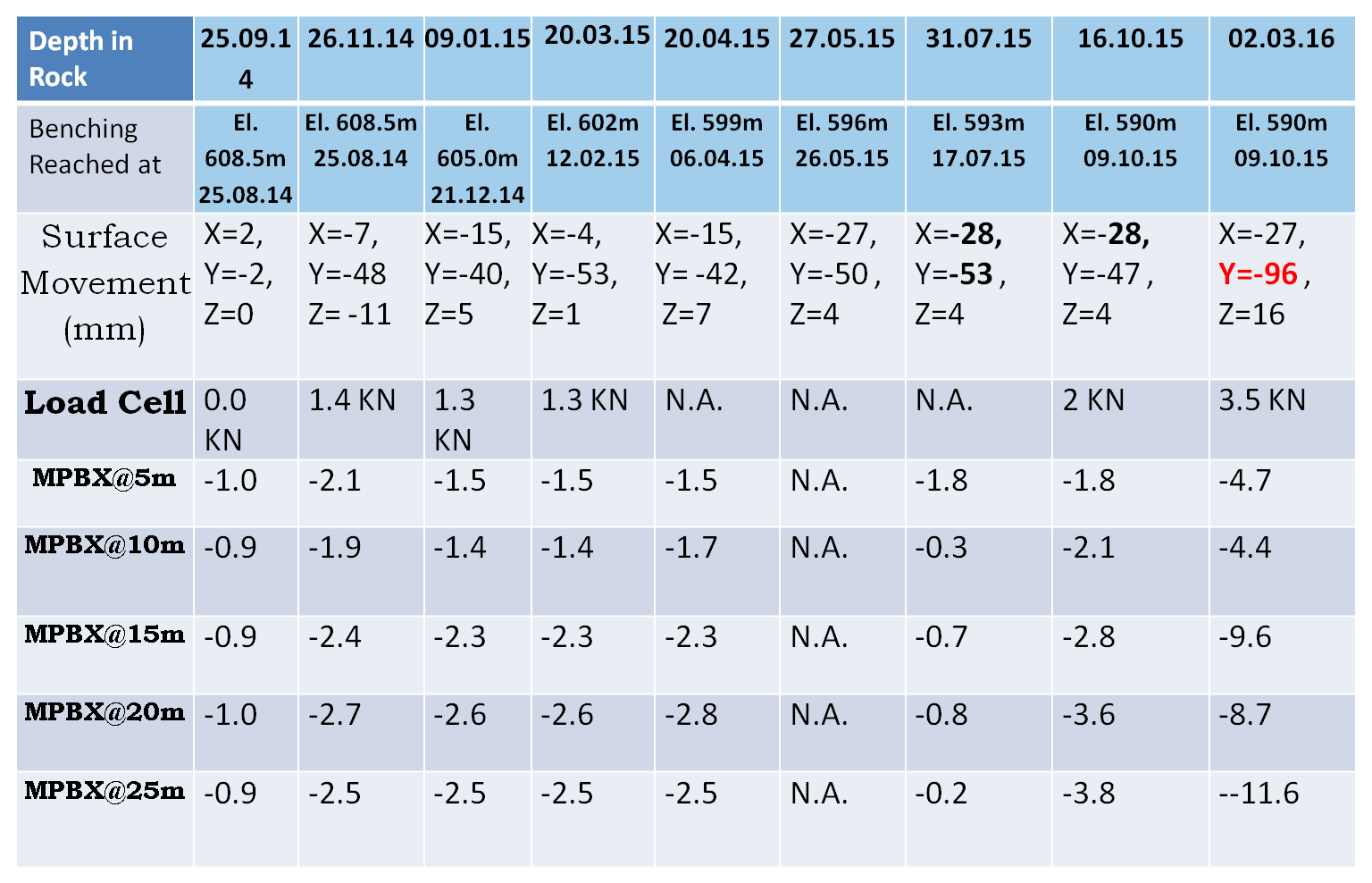
By 31.12.2015 when the benching proceeded to El. 587m in U/S wall and to El. 590m in D/S wall, the distress observed by MPBX in the crown remained insignificant. While distress in the U/S wall at Rd 135m at El. 609m got to the order of 5 to 8mm and that in the D/S wall increased to the order of 13.4 mm. While the distress observed by MPBX at RD 180m at El. 609m in the U/S wall had increased to 21.4mm and that in D/S wall had increased to the order of 27.5mm.
The important and much significant phenomenon observed is that ever since the benching had proceeded , the MPBX readings remained insignificant , thereby indicating that the displacement shown by the Surface Target meant that the rock mass above crown of the DSG cavern (at least up to a thickness of at least 25m of the rock above crown i.e. up to end of MPBX length) and the portion of walls lying above the intercept of shear plane, behaved like one body.
This upper truncated portion of the cavern separated along the inclined Shear plane and continuing in the walls of DSG towards North from the shear zone, had apparently started sliding bodily on the shear plane which dipped steeply from South to North direction and also dipped in other plane from U/S side wall to D/S wall.
The bodily movement of this truncated portion, along the shear plane is evident from the observation that while the MPBX readings remained insignificantly small, the Surface Target observed movement had been increasing very significantly.
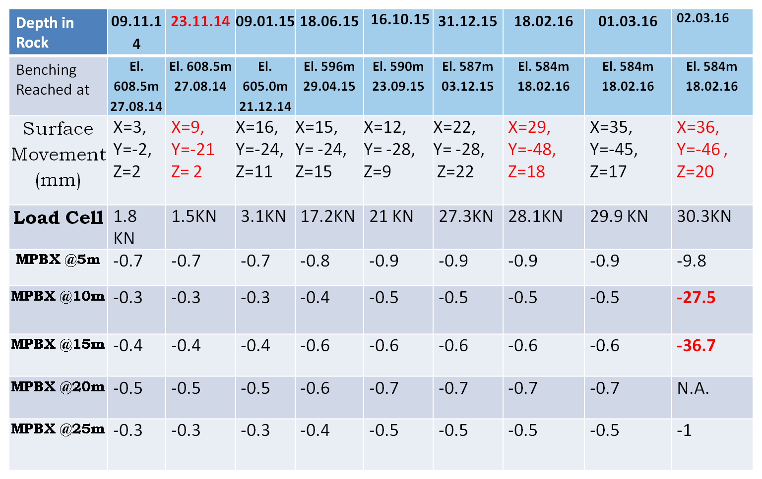
The readings shown by the MPBX instruments installed near the locations of collapse were almost constant for last 10 months and showed sudden increase in their readings on 02nd Mar, 2016. The reading of instrument installed at RD 135 at crown level (centre of the cavity) at El. 623.5m which was also constant till 01st March 2016 showed sudden increase from -0.5 mm to -1.0mm at 25m depth, -0.6mm to -36.7mm at 15m depth, -0.5mm to-27.5mm at 10m depth and -0.9mm to -9.8mm at 5m depth.
On 02.03.2016, the crown at RD 135m had drifted in direction from U/S to D/S walls by 36mm , had sunk by 46mm and drifted in direction from South to North direction by 20mm along the two dip directions of the shear plane.
At this time, on 02.03.2016 at RD 135m in crown the distress recorded by MPBX too had suddenly increased from less than 1mm earlier to 36.7mm sinking and at around 1.00am , the crown apparently due to failure of arch toe at SPL and below in a reach in which the Shear Plane intersected walls.
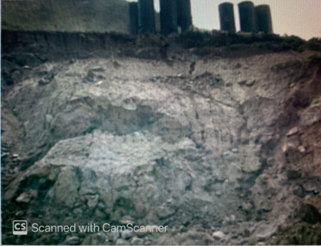
11. THE MASSIVE ROCK FALL – HAPPENED ON 03 MARCH 2016
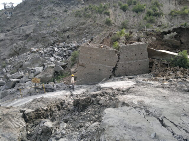
Massive rock mass failure happened from crown in Downstream Surge Gallery (DSG) between RD ±140m and RD ±210m, apparently, along a major shear zone (45ᵒ-60ᵒ/N030ᵒ) encountered at the crown portion between RD ±121m and RD ±140m and extending on the either wall dipping towards face (gable end wall). The failure of rock mass took place within a short period, starting on 3rd March, 2016 around 1.00am, leading to formation of huge cavity above crown. Six technicians working, at the time of the rock fall, in the DSG at locations between RD 140m to RD 210m, got buried under the falling rock muck and died. Bodies of only 3 of the dead were retrieved after removal of some muck from the toe of the piled up fallen muck.
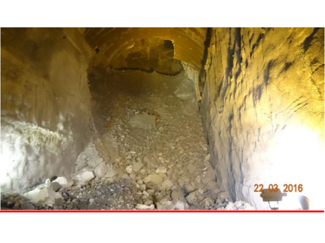
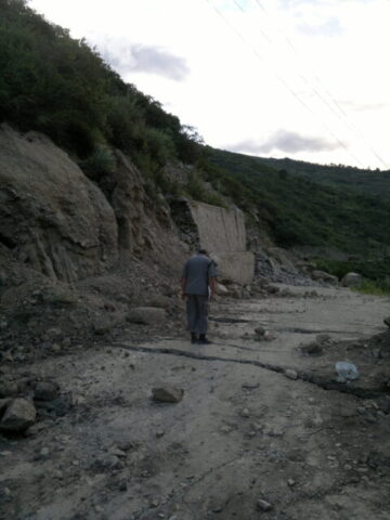
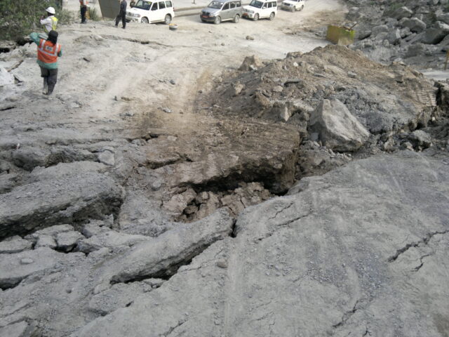
The loose fall from cavity had not stopped completely after the collapse on 03 March and intermittent loose fall continued for some three weeks. Rock After 03 March, the other loose fall from cavity had been recorded on 11/03/16 (Photo-2) and 22/03/2016. A portion of the cavity and hanging rock bolt became visible through a gap formed, after muck from top of the heap rolled down when some rock muck was removed from bottom at toe of the heap (Photo-3) in making efforts to retrieve dead bodies of the entrapped persons. The impact of the rock fall incident had been noticed in the nearby caverns/structures in the form of development of new cracks in the shotcrete, widening of already existing cracks particularly on the right wall of TH and Bus Ducts nos. 2 and 3.
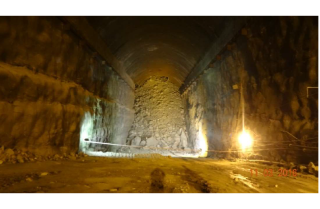
View of Rock Fall Muck Inside DSG, As Seen From Southern End of DSG, Which Blocked DSG At RD 140m Photo – 1
The construction Adit opens in the southern side of the DSG. The northern side of the DSG did not have any independent access. The northern half of the DSG got cut off from the southern side of DSG as the fallen muck blocked the DSG at RD 140m. Ten technicians who were working in the northern end of the DSG at the time of rock fall, miraculously escaped, after climbing the 45m high rock muck heap, from the small opening left at the top of the heap. However the small opening from where these ten technicians escaped had got blocked with further rock fall soon after they escaped.
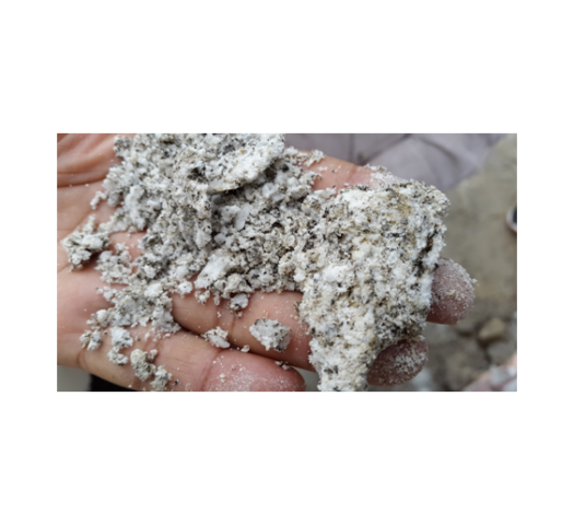
The fallen rock mass comprises variable size of fragmented rock pieces, sandy clay and dry clay fractions with big rock blocks (max. size ~9.0m x 1.5m x 3.0m). This clearly indicates that failure of rock mass is not restricted to only shear zone and its associated weak material, but the rock fall has been resulted from the loose fall, controlled by the gravitational forces acting on the blocks of rock comprising the rock mass and making them fall down as these disintegrated from adjoining blocks for being held together only weakly due to presence of clay content and crushed material in their joints and due to presence of intrusive pegmatite veins / bands.
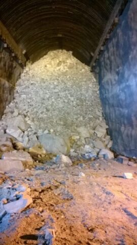
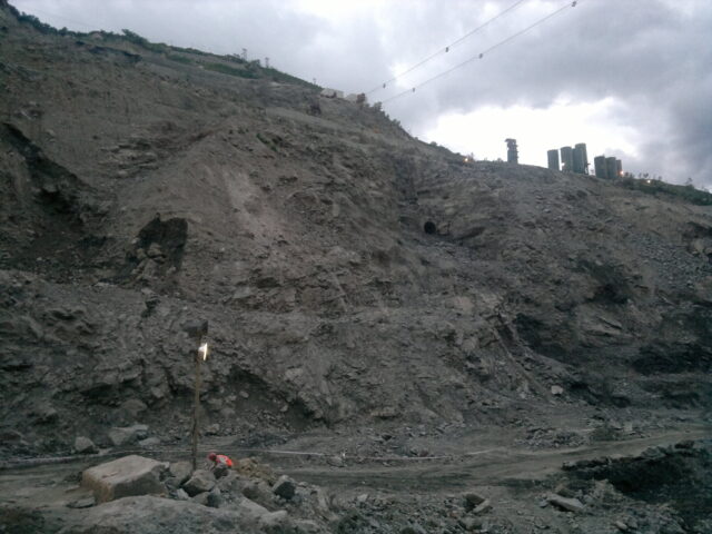
Rock Fall Status On 11.03.2016, After Some Muck Was Removed From Toe Of The Heap Photo – 2
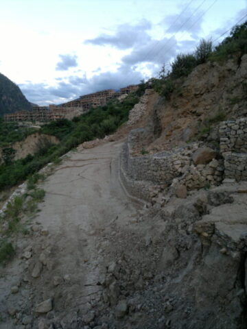
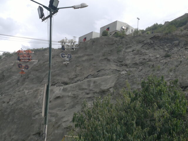
Rock Fall Status On 22.03.2016, A Portion of Cavity Is Visible Through A Gap Formed Due To Rolling Down Of Muck After Removal Of Some Muck From Bottom At Toe Of Heap Photo – 3
12. THE ASSESSMENT OF THE SIZE & ORIENTATION OF THE CAVITY FORMED
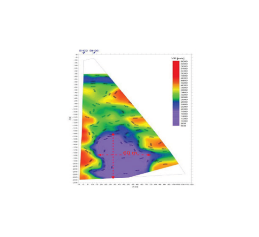
The size of the cavity and its orientation was assessed from a number of exercises including Seismographic Tomography, Lidar based Cavity monitoring using CMV 500 camera lowered from two number of 250mm dia holes drilled from ground surface above the location of cavity and a few holes done from the Cable Tunnel running parallel to the DSG.
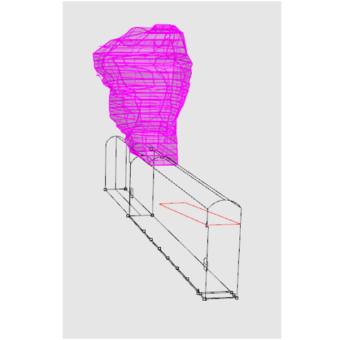
The above mentioned studies revealed that the massive rock mass failure which took place in very short time, did lead to formation of a huge cavity of 91m height x 45m width x 70m length above crown of the DSG Cavern.
3D View Sketch Of The 91m High x 70m Long x 45m Wide Cavity Formed Above DSG Cavern
Result Of Assessment Of The Cavity By Tomography
Fig. – 11
13. A Thorough Analysis Was Required To Check The Design Of Layout Of The Three Caverns For The Structural Stability, Under Conditions Of Actual Geology Including The Mega Shear Zone. If It Had Been Done Before Progressing With Excavation In Benching, It Would Have Established That Deeper Excavation Would Result In Widespread Yielding Of Rock Mass & Collapse :
The rock mass in the DSG in the Hanging Wall side of the Shear Zone in the DSG comprise thinly foliated, highly fractured biotite gneiss and crushed leucogranite/pegmatite.
A 3D Numerical Model Analysis done by an independent agency of repute has established that the rock mass lying over the Shear Plane from RD 145m to RD 195m suffered yielding, up to a thickness of about 10m to 15m inside the rock Pillar and the walls, while the DSG had been excavated only to about 45m of its full depth of 58.5m.
Rock Mass in DSG Pillar Yielded Up To 15m Thickness At RD 145m
Rock Mass in DSG Pillar Yielded Up To 15m Thickness At RD 155m
Wide Spread Yielding Of Rock Mass Around DSG At RD 195
Fig. – 12
Wide Spread Yielding Of Rock Mass Around DSG At EL. 600m
Wide Spread Yielding Of Rock Mass Around DSG At EL. 610m
Wide Spread Yielding Of Rock Mass Around DSG At EL. 620m
Fig. – 13
14. The Possible Explanation Of The Phenomenon Leading To The Massive Rock Mass Failure
Surface BRT Readings v/s MPBX Distress Readings At Crown At RD 135m:
Readings At EL. 623.7m At Center In The Crown At RD 135m
The reading of MPBX instrument installed at RD 135 at crown level at El. 623.5m which was constant till 01st March 2016 showed sudden increase from -0.5 mm to -1.0mm at 25m depth, -0.6mm to -36.7mm at 15m depth, -0.5mm to-27.5mm at 10m depth and -0.9mm to -9.8mm at 5m depth, When the Surface BRT Instrument showed the crown having displaced in X-Direction from Upstream to Downstream wall side by 36mm, Y- Direction (Settlement) by 46mm and Z-Direction towards Northern Gable end by 20mm .
Surface BRT V/s MPBX Readings At EL. 620m In Crown At RD 135m In Upstream Wall
Surface BRT V/s MPBX Readings At EL. 620m In Crown At RD 135m In Downstream Wall
The reading of MPBX instrument installed in the crown arch at RD 135 at El. 620m in Upstream Wall which was not very significant till Jun 2015 started increasing thereafter and became quite significant by Oct 2015 and the distress still increased reaching to the order of 20.5mm and in the Downstream wall side MPBX at El. 620m at the RD 135m the distress which was insignificant, it increased suddenly on 02 March 2016 to 11.6mm, When the Surface BRT Instrument showed the the arch at El 620m having displaced in X-Direction Upstream to Downstream wall side by 27mm, Y- Direction (Settlement) by 96mm and Z-Direction towards Northern Gable end by 16mm .
* Reference : Under Ground Excavations in rock by Hoek & Brown/ page 210
“In case of an inclined over-body, the shear stress being parallel the dip of the over-body, gives rise to asymmetrical stress distributions. This asymmetry is even more pronounced when excavations are influenced by gravitational loading (from structurally poor rock mass matrix)”.
Norwegian geotechnical institute, which was assigned to suggest strengthening measures after rock mass failure, has in its report mentioned that “in the area of cavity in DSG ( i.e. Shear zone affected area), the pillars are more loaded” . (i.e. Indicating loaded beyond their capacity )
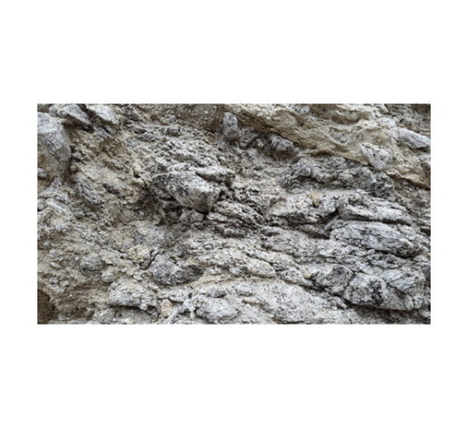
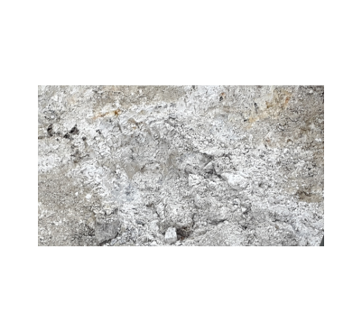
It has been noticed that in the shear zone thinly foliated, highly fractured biotite gneiss and crushed leucogranite/pegmatite is exposed particularly on the left wall near SPL at RD 124m to RD 140m . Further at the crown near RD ±170m blocky and jointed rock mass is exposed.The rock mass quality in PHEP-II is Poor to Very Poorformed of fractured and blocky rock mass comprising Quartzo feldsphatic biotite gneiss / biotite gneiss/ micaceous quartzite with leucogranite & pegmatite, minor shear seams , thinly foliated rockmass with low dipping foliation (10ᵒ – 25ᵒ / N200ᵒ – 230ᵒ) joint at places. The major shear zone (45ᵒ-60ᵒ/N030ᵒ) encountered at the crown portion between RD ±121m and RD ±140m is extending above the crown and below on the either wall dipping towards face (gable end wall).
The massive rock mass failure took place in very short time leading to formation a huge cavity above crown (Fig. – 11). The fallen rock mass comprises variable size of fragmented rock pieces, sandy clay and dry clay fractions with big rock blocks (max. size ~9.0m x 1.5m x 3.0m) which clearly indicates that failure of rock mass is not restricted only to shear zone and its associated weak material.
* It can be explained that the shear zone material and associated weak rock mass fell down first. Later on the jointed and blocky rock mass, which was abutting along the plane of the shear zone and structurally being just an assemblage of rock blocks, it was bound to slide/fall down under its gravitational force due to removal of its toe. Large blocks of parent and intrusive rocks fell down (intermittently) for the last 20 days resulting into formation of huge cavity (±50m) above the crown (EL ±623.70m) tentatively between RD ±130m & RD ±170m. The lateral and vertical extension of cavity towards gable end wall is because of slabbing and wedge.Large blocks of parent and intrusive rocks kept falling down subsequently as the cavity propagated in its height to 91m, in length to about 70m and in width to about 45m.
The Norwegian Geotechnical Institute has mentioned in its findings that the ribs do not show any sign of deformation and the rock pillars are more loaded. The fact that failed/fallen ribs do not show any sign of deformation (bending/shearing/twisting), clearly indicates that ribs have failed due to sudden impact of overlying dead load, which was resulted from settling of the yielded rock mass in the Pillars and thus failing the toe of the ribs at SPL.
The toe of the ribs rested on the yielded rock pillars which were already weak because of their provided thickness of 40m only, which was less than the norm of thickness advised by International Research Papers and as such required to be 52m. Further the pillar were weakened by the intersecting mega shear zone. Therefore with the sudden impact of sudden development of the dead gravitational load in the crown due to sinking of its supports , the toe at SPL of the ribs failed.
15. THE CRUCIAL REVIEW WHICH WAS MISSED BY THE DESIGNER/ CONSULTANTS, WOULD HAVE WARRANTED SHIFTING OF DSG OR ALTERING ITS LAYOUT TO AVOID ITS INTERSECTION BY THE SHEAR ZONE
A critical decision about the site of the PH Complex, which was required to be reviewed by the Designer / Consultants at the time when the site conditions and the encountered geology were reported to the Designers/ Consultants time after time, is discussed below citing reference from the International Literature of the renowned author :
Conceptual Visualization Of Shear Zone Cutting The Hill
Fig. – 14
15.1 The Shear Zone encountered in the Construction Adit of DSG & Main Access Tunnel to the PH Cavern earlier in 2013 were indicative of its intersection of the three caverns :
The shear zone along which apparently, the failure of rock mass has taken place had been identified prior to excavation of DSG and it was delineated in Adit to DSG (at RD ±440m) and Main Access Tunnel (at RD ±420m) in the year 2013.
15.2 The same shear zone when was encountered in the crown of DSG between RD ±121m and RD±129m, the Project Authority advised the Designers / Consultants to shift the location of all the three caverns of PH, TH & DSG to avoid their intersection by the Shear Zone :
During excavation of central gullet of DSG the same shear zone was encountered in the crown of DSG between RD ±121m and RD±129m at crown level (EL ±623.70m). The Resident Geologist, at that time, made an assessment of the intersection of this major shear zone and influence of its associated zone. Taking note that the steeply dipping Major Shear Zone will be cutting the PH and TH that too for their entire depth,the Project Geologist suggested for shifting the location of all the three caverns, to avoid their intersection by the Shear zone.
However as per the instructions of the Designers / Consultants, only the Machine Hall and Transformer Hall caverns were shifted towards backwards (N190ᵒ direction). Along shear zone water seepage had also been recorded (central gullet) which had lowered the shear parameters. The shear zone (attitude; 45ᵒ- 60ᵒ/N030ᵒ) has associated rock mass classified as class V (Q – 0.19 – 0.58). Over breaks of the order of 4.0m to 8.0m were observed between RD ±121m and RD ±129m in the Central Gullet. During excavation of central gullet a cavity (7m-8m) was formed at crown level and it was back filled with concrete and rock mass grouted before widening. The entire zone was supported with steel ribs.
During slashing/widening of the DSSC no adverse effect such as cavity formation, distressing in rock mass and disturbance/deformation in already erected ribs were noticed / recorded.
However, during November 2014, when the benching was progressing in the Shear Zone and its affected zone, sinking of the steel ribs at SPL line were noticed on the DSG wall near shear zone and it was communicated to the Designers/ Consultants. The gap created in the concrete pad and the rock profile in the affected reach was filled back and grouted as advised by the Designers / Consultants.
* INTERNATIONAL LITERATUREWARNS THAT : “STEEPLY INCLINED STRUCTURAL GEOLOGICAL FEATURES & FAULTED /JOINTED ROCK MASS MAY WARRANT RELOCATION”
* Reference : UNDERGROUND EXCAVATIONS IN ROCK by HOEK & BROWN (Page 10 & 11):-
” Instability due to adverse structural geology tends to occur in hard rocks which are faulted and jointed and where several sets of discontinuities are steeply inclined. Stability can sometimes be improved by relocation or reorientation of the excavation but fairly extensive support is usually required. Rockbolts, dowels and cables are particularly effective, provided that the structural features are taken into account in designing the support system.
If stability cannot be improved by reorientation / relocation and design of support to prevent gravity falls to reinforce potential fracture zones is not possible, theSITE BE REJECTED. “
Taking note that the steeply dipping Major Shear Zone will be cutting the PH and TH that too for their entire depth, the Project Geologist suggested for shifting the three caverns, to avoid their intersection by the Shear zone.
The Design Consultants shifted only the PH & TH caverns to avoid major Shear Zone from intersecting these caverns.
Designers still preferred the huge sized single gallery. The site of DSG was neither rejected nor bifurcated or shifted to avoid shear zone and the fractured zone
Provision of cable anchors suggested by Project Authority for improving structural stability were specifically denied by Design Consultants
CRUCIAL ACTION REQUIRED BUT MISSED WAS:
As the major shear zone was to intersect all the three caverns throughout their entire depth, thus beside shifting the location of TH & PH, it was also prudent to at least bifurcate the DSG in to two chambers with the middle reach of DSG from RD 130m to RD 180m intersected by shear zone, been left un-excavated. Additionally small interconnected galleries could be provided to make up for volume lost in thus abandoned middle reach.
16. IS THE PRESENT SITE OF THE PH COMPLEX OF PHEP-II SAFE ??
Actually in the DSG which is aligned in North-South direction, the Shear Zone cutting it across, separates a relatively good rock mass occupying in its southern side, from a fragmented rock mass with sub-horizontal foliation, intruded with lenses & inter-bedding of altered & weak material like crushed pegmatite occupying its northern side.
The rock massin the DSG Occupying its northern side of the partition made by the Shear Zone, behaved like an assemblage of loosely packed rock blocks forming the hanging wall, which when were rendered unconfined along its face abutting the Shear Zone and crown surface , were bound to slide/fall down under its own gravitational load, due to removal of its toe. Large blocks of parent and intrusive rocks fell down (intermittently) for the 20 days resulting into formation of huge cavity (±91m high) above the crown (EL ±623.70m) tentatively between RD ±140m & RD ±210m. The lateral and vertical extension of cavity towards gable end wall is because of slabbing and wedge formations.
However, the most important point is that after the sudden formation and fast propagation of the cavity to a height of 91m and its spread in about 70m length and about 45m width, the huge cavity and its surrounding rock mass is lying, for more than 4 years, unattended and untreated and without getting strengthened. What would be the condition of the rock mass surrounding the cavity ? The Tomography study indicates that a bigger zone surrounding the profile of the cavity is disturbed.
What should be the extent of strengthening the rock mass surrounding the cavity and the walls of caverns of the DSG, TH and PH so as to make this site safe for about 100 years of the life of the Project ??
Series’ Next “Surprise” -The Unexplored Mega Shear in Punatsangchhu-II Dam
– Another Dam Location That Too May Go / Have Gone / Could Have Gone Wrong Due To Unexplored Shear Zone Called “Geological Surprise”. Could This Shear Zone, If Went Unexposed, Have Repeated A Punatsangchhu-I ?
( Second of the incidences of a chain of massive surprises in the two Punatsangchhu Projects in Bhutan )
* Are All Geological Surprises, Logical Geo Surprises ?
In the series of strange coincidences of “geological surprises” , which happened in the two mega hydroelectric projects named Punatsangchhu -I & Punatsangchhu-II H E Projects, under construction since 2009 -10 in Bhutan, the present case is of a suddenly encountered mega Shear Zone, which cuts across from heel to toe, the foundations of four dam blocks, in an effective width maximum of 30m and running in depth more than 13m. This surprise came despite the very dam site having been explored by the Consultants in the DPR ( unlike the case of Punatsangchhu-I dam where a mega shear zone was ‘surprisingly’ encountered supposedly because the dam site was not the one, which was studied by the Consultants in DPR).
The structural damage control seems to have been done with shear zone treatment , but at a great cost both in terms of the big time delay of more than one year and extra cost of Rs. 387 million, put to the Project in exploring the shear zone and treating it. However, the success of the Shear Zone treatment would be tested with time.
The Punatsangchhu-II (PHEP-II), a 1020 MW project with a new approved project cost of Rs. 72900 millions ( US $ 1.04 billions), possibly to be further escalating to Rs. 75000 millions ( US $ 1.07 billions), with already incurred cost of about Rs. 65880 millions is delayed for two reasons. Firstly the delay of more than one year was caused because the Dam foundations had encountered, a that far unexplored,mega shear of maximum 30m width, which cut across the length of the 4 dam blocks diagonally, traversing from heel to toe. The shear zone with its 35ᵒ to 45ᵒ dip, continued under the foundations to large depths. Secondly, a further delay of four years, so far, in implementation of the Power House Complex, has already crept in due to the huge rock mass failure which happened in its underground Downstream Surge Gallery (DSSG), resulting in formation of a huge cavity of about 91m height x 70m length and 45m width in the crown of the DSSG.
Occurrence of too many geological surprises, which were blamed for the big mishaps in the two mega Projects Punatsangchhu – I & II ,intrigues one to investigate if ‘ harping on thegeological surprises‘ was only a scapegoat for the lack of proper geological investigations done by the Consultants and inappropriate design of rock support measures done by the Designers, who were same for both the Projects.
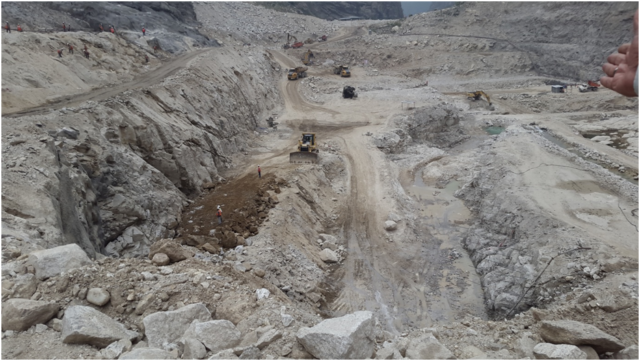
The Case of Mega Shear Encountered In PHEP-II Dam Foundations
1. Geology at Dam Site :
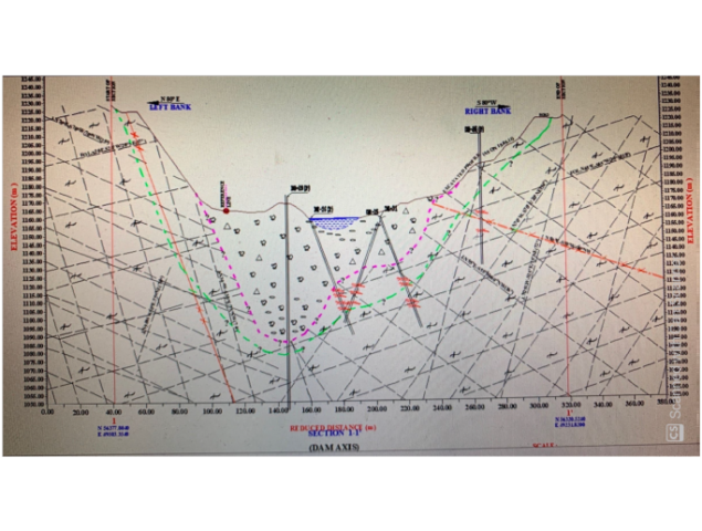
Geologically, the area at the dam site exposes variety of gneissic rocks such as quartzo-feldspathic biotite gneiss, banded gneiss, augen gneiss, and thin seams or bands of biotite schist. These rocks are intruded by leucogranite and pegmatite. The right bank is comparatively steeper and occupied by well exposed rock outcrop. Whereas the left bank is largely occupied by overburden consisting of talus and thick slide debris with some rock outcrop exposed at higher reaches. On the left bank foliation trend varies from N-S/400E to N700E-S700W/150SE whereas on the right bank it varies from N800W-S800E-320/S100W to N500E-S500W/300-350 S400E. This swing in foliation is due to warping in the rock. However the general trend of the foliation is N600-700E to S600-700W/300SE. The rocks are moderately to highly jointed, traversed by four to five prominent joint sets and shear zones up to 50cm thick. In general the foliation is dipping into hill side; indicates an anti-formal structure.
2. Geological Investigations at ‘Detailed Project Report’ Stage Failed To Detect The Major Shear Zone In Dam Foundations
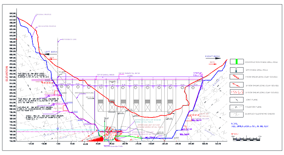
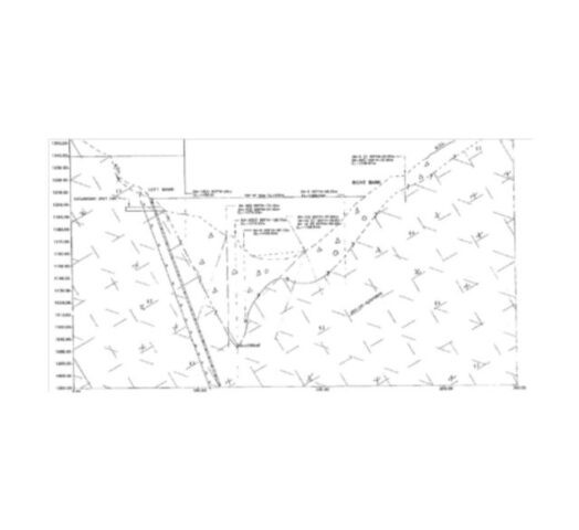
In the DPR stage, in the geological investigations carried out by the Consultants, a total of 11 nos. of holes were drilled at the proposed dam location for ascertaining the rock-overburden contact and depth of fresh rock for deciding the foundation level of various blocks. On the basis of these DPR stage drill core examination, the deepest foundation was proposed at EL 760.0m by the Consultants in the DPR. No major Shear Zone were detected to be present at dam site as per DPR stage explorations and geological investigations done by the Consultants (See Fig. -1).
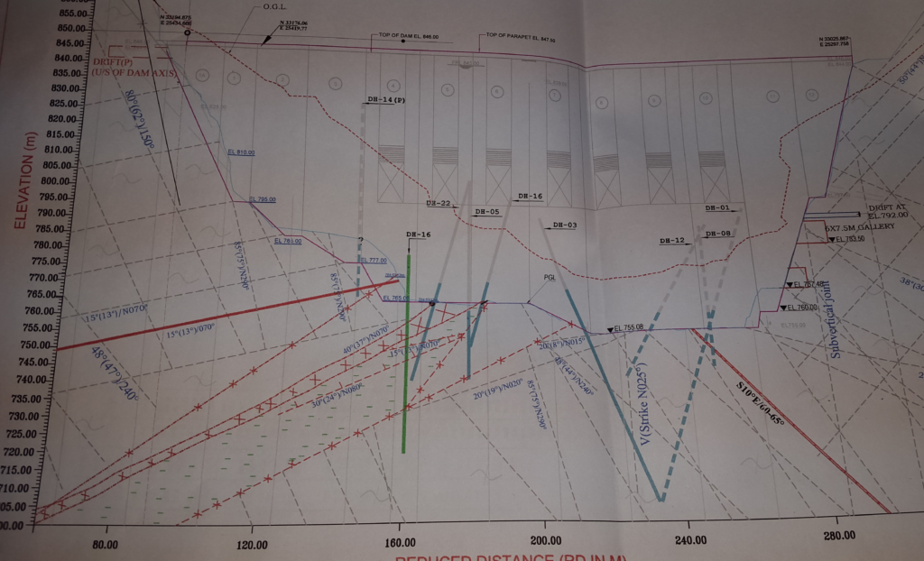
Geological Section At DPR Stage – Shows No Shear Zone Under Dam Foundations Fig. – 1
3. Geological Investigations At Construction Stage :
Weak features were encountered during dam excavation /stripping of the left bank, which were not reported in the DPR stage investigations done by the Consultants. Actual rock profile at EL 825.0m, in the Left bank was found shifted by 14.5m towards hill side from that suggested by DPR stage investigations .
In view of this discrepancy a detailed investigation was felt required to be done to ascertain the sound foundation grade rock and to also decide stripping limit. Subsequently, during construction stage, keeping in view the change in anticipated rock slope profile, 12 nos. of drill holes ( See Fig.-3) were drilled at EL 825m to reconfirm the rock overburden contact and foundation grade rock at the dam bloc nos. 1, 2, 3, 4 & 5 located near the left abutment. As the fresh rock was encountered at higher level as compared to DPR stage investigations, the of block nos. 4, 5, 6, and 7 have been founded at EL 765.0m, instead of at EL 760.0m.
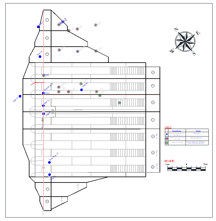
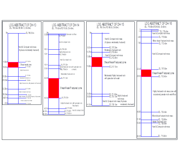
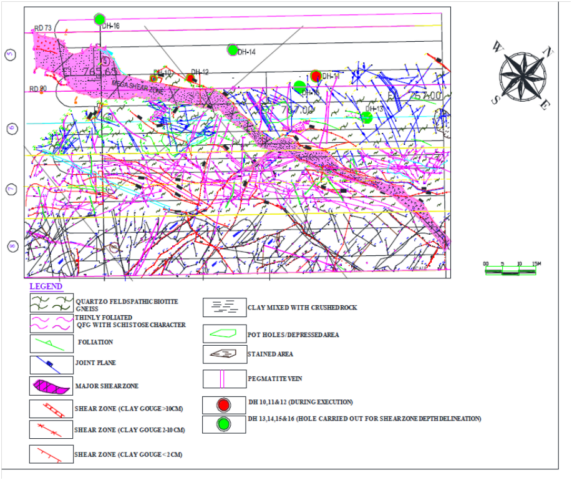
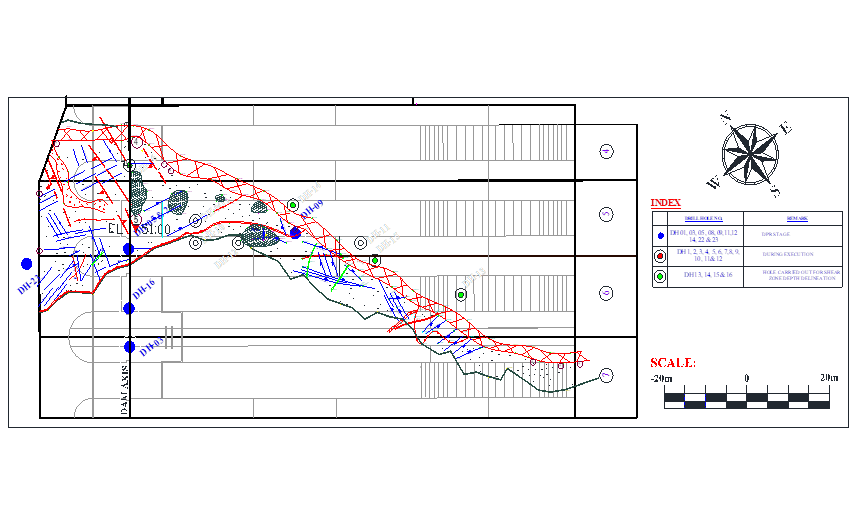
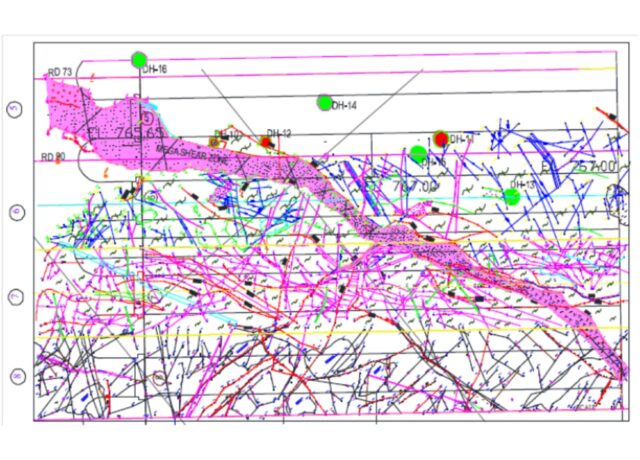
During these construction stage exploratory drilling, on the left abutment, weak rock mass zone with sandy horizon encountered in the DH-10 and 12 ( See Fig. 3). From the drill core logging it had been interpreted that sand and crushed rock pocket exists from EL 763.4m to El 759.40m, however that time direction and inclination could not be confirmed.
The drill holes in the river bed area established to have a maximum depth of fluvial fill material/overburden of 52.50m (DH-9: located in block no. 5, 35m d/s of dam axis). The maximum depth of the quaternary alluvium/overburden in the river valley under the dam axis is 45.60m (DH-14: located in block no. 3, at dam axis).
General level of the exposed bedrock in the overflow dam section varied from EL 765.0m in dam block no. 4 to EL 755.0m in main dam pit (block nos. 8, 9, 10). The rocks exposed at the foundation grade comprised predominantly quartzo-feldspathic-biotite gneiss, biotite gneiss, and leucogranite. These were intruded by veins of leucogranite, quartz and pegmatite. The foundation rocks were traversed by a number of shear seams and most of them were of short continuity and restricted to a single dam block.
* Still no major Shear Zone was detected in this detailed geological investigations done by the Consultants during excavation of dam pit.
4. Additional Geological Exploratory Drilling Necessitated Yet Again During Further Dam Excavation
As mentioned above, 12 nos. of holes were drilled during excavation stage in view of the discrepancy observed against the DPR investigations. A 4.0m thick sand pocket was found resting over highly fractured and crushed rock mass near proposed joint of block nos. 5 & 6 when had been probed during drilling of hole nos. 10 & 12 at RD 87.0m & CH 16.0m & 27.0m respectively below proposed block joint of 5 & 6. Considerable water loss was observed during drilling and sand was first appeared at EL 763.0m during drilling hole no. 10 and continued up to EL 758.5m. The rock strata encountered immediately below sand deposit was found highly fractured and crushed up to the EL 749.90m. The same sand deposit was further reconfirmed through hole no. 12 drilled at RD 87.0m & CH 24.0m downstream where it is appeared from EL 760.27m to EL 758.77m,resting over highly fractured and crushed rock mass up to EL 755.77m. In view of uneven bed rock profile four drill holes were carried out to decipher the sound foundation grade rock below the EL 822.0m and on the basis of interpretation of borehole core logs, the dam block no. 1 was lowered up to EL 795.0m (instead of EL 825.0m) and block no. 2 rested at EL 785.0m (instead of 798.0m).
Subsequently, during further progress of excavation on left bank of dam being done concurrent to drilling of above mentioned additional four holes, a shear zone (550-600 / N0700 to 0900, affected zone varies from 3.5m to 5.6m, Clay gauge >20cm, with crushed/fractured rock mass) encountered askew to the river flowing direction passing from u/s to d/s (heal to toe of the dam).
The Shear zone was encountered in all these additional four drill holes at different depth with variable thickness.
5. Investigations, delineation and interpretation of the Shear Zone
With the progressive excavation, when the excavation in block no. 6 & part of block nos. 5 & 7 excavation (EL ~765.50m) was in progress the major shear/weak zone was encountered in all these blocks.
Sub-surface investigation was done through those additional four boreholes, mentioned earlier above (DH-13 to DH-16), with total depth of 187.0m, drilled on the dam site (dam foundation blocks 4, 5, 6 and block joint of 5 & 6), to ascertain the thickness, depth and behaviour of the shear zone. Frequent change in attitude of shear zone, was observed.
Layout Plan of Exploratory Holes in Dam Area Blue Points – DPR Stage Holes, Red Points – Construction Stage Holes, Green Points – Additional Holes Done in Construction Stage for Delineation of Shear Zone Fig. – 2
Shear zone with varying thickness of clay gouge material and affected zone (approximately 3.5m to 6.5m) was encountered in the main dam pit area in the block no. 8 (at EL ~755.0m: near toe of dam body) and in the inclined foundation of the dam block no. 7 (below EL 765.0m) and below dam block nos. 5 & 6.
Shear Zone – Drill Core Log Abstracts For DH13, DH14, DH15 & DH16 Fig. – 3Geological Section Along Dam Axis Showing the Orientation Of The Mega Shear Zone Intercepted In Additional Holes Done During Excavation In Blocks 5,6 & 7 Fig. – 4
The encountered rock mass, in the drill holes, comprises predominantly quartzo-feldspathic-biotite-gneiss (QFBG), biotite gneiss, leucogranite with bands of biotite schist of variable thickness. At places the rock mass is intruded by thin veins/patches of pegmatite. Shear material mainly comprises highly pulverized rock mass, granular rock flour, fractured rock mass, clay gouge with slush, and broken rock fragments.
The drill core logging revealed that the shear zone depth varies from 3.1m to 11.22m and affected/fractured rock mass zone below the shear zone varies from 6.0m to 20.0m in depth.
The shear zone is traversing from dam heal (block no. 5), dam centre (block no.6) to dam toe (block no. 7) having curvilinear nature, however, it is encroaching in block no. 4 by ±1.0m near RD 73.0m in a limited area; between CH ±18.69m and CH ±20.0m at EL 765.0m and in block no. 8 d/s portion it is intersecting between CH 97.0m and CH.102m at El 755.0m. The general trend of shear is 350-420/N 0700 to 0800.
Geological Plan Of The Mega Shear Zone That Cuts From Heel To Toe Across Dam Blocks 5,6,7 & 8 Fig. – 5
However, there is variation in the shear’s attitude due to warping of foliation and its curvilinear nature. In the block no. 5 the thickness of shear zone (including fracture zones and affected zones) at the dam axis is 13.97m whereas, in the u/s part of the dam (near CH ±20.0m) it is 14.19m thick. Sheared material comprises moist clay gouge (0.5m to 1.0m thick), rock flour, crushed/fractured rock, fragmented rock pieces and intermittently hard patches of parent rock (no strain zones). The affected zone varies from 4.0m to 30.0m.
The foundation surface in the mapped area is undulatory due to intersection of different joint sets and formation of wedges. The geological mapping revealed that the mega shear zone is bounded by two shear zones (SZ-1, forming left side boundary, having clay gouge thickness 5cm -20cm and SZ-2, forming right side boundary, having clay gouge thickness 8cm – 100cm) passing through block nos. 5, 6 and 7 from upstream to downstream direction, dipping into left abutment side, and having variable thickness.
Infilling material of this weak zone comprises crushed rock mixed with minor clay and at places small lenses/chunk of QFG. The width of this zone varies from ±7m, at u/s side near dam axis, to ±2m at d/s side. The attitude of its two boundaries i.e. SZ-1 (200-550/N0700-1000) and SZ-2 (200-550/N0500-1100 also vary from u/s direction to d/s direction at different places. Besides, major shear there are 13 nos. shear seams were recorded during foundation grade mapping.
Geological Sections Depicting Varying Attitude Of Shear Zone In Different Dam Blocks at Dam Axis and at Ch. 40m, 60m and 80m D/S of Dam Axis Fig. – 6
Photographs of Shear Zone
Highly Pulverized rock mass, granularrock flour, fractured rock mass, clay gouge with slush and broken rock fragments
Sheared material comprise moist clay gouge ( 0.5m to 1.0m thick), rock flour, crushed/ fractured rock, fragmented rock pieces and intermittently hard patches of parent rock
6. Treatment of the Shear zone
Finally, a 125.0m long, 5.0-35.0m wide and 13.0-15.0m deep shear trench was made in order to treat the shear. The field observation suggests that this shear is a discrete fracture between blocks of rock containing several parallel or anatomizing(i.e. branching and reconnecting) shears particularly at the toe of dam body near dam block nos. 7 & 8 and may have formed in brittle ductile regime.
Cross Section at Dam Axis Showing Trench Cut In The Shear Zone Fig. – 7Geological map of the Shear Trench Floor Fig. – 8
Photographs of Shear zone trench excavation
Shear Trench And Rock Anchors Provided in Trench Walls
Typical Drawing of 13m Thick RCC Raft PlugWith 6 Layers of Reinforcement Fig. – 9RCC Plug in Shear Zone Showing Top Layer of ReinforcementBefore Concreting
* The Shear Zone though has been replaced in its depth of 13m by RCC Plug, its performance with time would need to be watched.
The consultants had failed to detect and delineate the Mega Shear Zone in the Geological Investigations which formed the basis of selection of the respective Dam Sites, in both the cases of Punatsangchhu-I and Punatsangchhu-II HE Projects. In the case of Punatsangchhu-I a major slide of right bank on the shear zone has halted the dam construction by 7 years as of present. In the case of Punatsangchhu – II, the detection, delineation and treatment of the shear zone delayed the dam construction by more than a year. The treatment and strengthening of shear zone in both cases has made huge time and cost over run in the Projects.
The excavation of the Shear Zone involved excavation of 43 million cubic metres in sheared rock/ fractured rock mass. The Shear Zone trench was refilled by M25 grade and M20 grade of cement concrete provided with 2200 MT of 32mm dia. steel reinforcement . The consolidation grouting done through combination of Multi Stage and Single Stage grouting in the shear zone area, as per my information, consumed 8 bags of cement per hole, thus aggregating to total consumption of 9297 number of cement bags. The grout acceptance experience in the affected area after excavation of the Shear Trench gives an indication of the clay content in the fractured rock material present under the shear zone. The Shear Zone treatment has costed Rs. 387 million and more than a years delay to the Project.
The Shear Zone was missed by the Consultants in the drill holes no. DH5, DH9, DH10 , DH 12 and DH22 which were done in the Dam Block no. 5 at DPR stage and later in initial construction stage, despite their location being almost the same as that of additional four holes DH13, DH14, DH15 & DH16 in which the Shear Zone was intercepted at the end during excavation at the behest of Project Geologist and Project Engineering and Construction Agency team.
The massive Shear Zone had been finally detected and treated.
* However, the debatable point is that if the presence of this massive Shear Zone of that great a size , which affected foundations of four numbers of dam blocks from heel to toe, in a maximum width of 30m and depth more than 13m , had been detected at DPR stage, then, should this very site been preferred as dam site ?
* In case the answer is NO, then whether construction of the dam here at this site is a compromise of a sort ?
The detailed paper co-authored by me “Delineation and treatment of Mega shear zone in the main dam foundation : A case study of Punatsangchhu HEP-II, Bhutan” was selected for 26th ICOLD Congress” held in July on 1-7-2018 at Vienna, Austria. The Paper was also selected for oral presentation.
( Second of the incidences of a chain of massive surprises in the two Punatsangchhu Projects in Bhutan )
Dirty Water in Delhi
B.Tech Project. BTP Supervisor: Prof. Manohar Khushalani
According to the 2018 NITI Aayog Report, Delhi is among 21 Indian cities that is poised to run out of groundwater by 2020. It has also been reported that Delhi has been drawing 25 percent more groundwater than the natural recharge rate. Though it is the job of Central Ground Water to stop the exploitation of groundwater, their actions have not been effective. 60 percent of the water supplied by Delhi Jal Board comes from the Yamuna, around 34 percent from Ganga, and the rest is from groundwater. Yamuna river, the major provider of the city’s drinking water, runs heavy with pollutants and is thick with toxic waste and it becomes toxic because of all the sewage that is dumped into the river.
Manohar Khushalani, Rajeev Babar, Kuldeep Kumar and Sanjeev Kaushik were the four panelists invited for this discussion, for an expert opinion, on the dirty water problem faced in Delhi. This video gives an insight into the perspective of the general public and how they’re facing this problem.
TV9 has conducted surveys in 8 parts of Delhi, namely, Laxmi Nagar, Sangam Vihar, Chandni Chowk, Lajpat Nagar, Pitampura, New Delhi, Narela, and Yamuna Vihar. During this survey, they have asked people about their opinions on a few questions about the water and air pollution in Delhi. More details on this is given below.
They had also collected water samples from these areas and gave it for testing. After the results came out, they found out that all the samples that were collected from the 8 parts of Delhi which were surveyed had contaminated and undrinkable water.
Questions asked by TV9 to general public:
Is the water that you receive dirty or unfit for drinking?
Yes
No
Don’t Know
Laxmi Nagar
80%
7.5%
12.5%
Sangam Vihar
75%
15%
10%
Chandni Chowk
80%
15%
5%
Lajpat Nagar
80%
16%
4%
Pitampura
57.5%
35%
7.5%
New Delhi
90%
5%
5%
Narela
92.5%
5%
2.5%
Yamuna Vihar
45%
40%
15%
This means that on an average, 75 percent of the people said yes, that the water they receive is unfit for drinking, 17.3 percent said no, the water they receive is fine and the rest of 7.7 percent said they’re not sure.
Does the dirty water make your family fall ill?
Yes
No
Don’t Know
Laxmi Nagar
75%
7.5%
17.5%
Sangam Vihar
82.5%
12.5%
5%
Chandni Chowk
72.5%
10%
17.5%
Lajpat Nagar
70%
20%
10%
Pitampura
55%
40%
5%
New Delhi
90%
7.5%
2.5%
Narela
95%
2.5%
2.5%
Yamuna Vihar
50%
47.5%
2.5%
This means that on average 73.8 percent of the people said that yes, the dirty water makes some of the family members fall sick, 18.4 percent said no, it doesn’t make them fall sick, and the rest 7.8 percent said they’re not sure.
Do you want to leave Delhi because of the water and air pollution?
Yes
No
Don’t Know
Laxmi Nagar
52.5%
42.5%
5%
Sangam Vihar
75%
17.5%
7.5%
Chandni Chowk
70%
25%
5%
Lajpat Nagar
60%
36%
4%
Pitampura
32.5%
65%
2.5%
New Delhi
55%
32.5%
12.5%
Narela
70%
7.5%
20%
Yamuna Vihar
37.5%
47.5%
15%
This means that on an average, 57 percent of the people said yes, they want to leave Delhi, 34.1 percent said no, they’d like to stay there itself and 8.9 percent of the people said they’re not sure.
Do you feel the air in your locality is still polluted and it’s becoming hard to breathe?
Yes
No
Don’t Know
Laxmi Nagar
82.5%
15%
2.5%
Sangam Vihar
80%
15%
10%
Chandni Chowk
85%
10%
5%
Lajpat Nagar
68%
30%
2%
Pitampura
82.5%
12.5%
5%
New Delhi
92.5%
2.5%
5%
Narela
90%
2.5%
7.5%
Yamuna Vihar
87.5%
7.5%
5%
This means that on an average, 83.5 percent of the people said yes, they feel the air is polluted and it is becoming hard to breathe, 11.8 percent said no, they do not find it hard to breathe and the rest 4.7 percent said they’re not sure.
Lok Sabha TV conducted a panel discussion on the study on Water Management of the Indus River System and its Implications for India’s Foreign Policy. The invited panelists were Prof. Manohar Khushalani, Sushant Sari and Akshay Singh.
Manohar Khushalani started the discussion by describing the Indus Water Treaty.
The Indus Waters Treaty is a water-distribution treaty between India and Pakistan, brokered by the World Bank, to use the water available in the Indus System of rivers. It was signed on 19 September 1960 by Jawaharlal Nehru, the then Prime Minister of India, and Ayub Khan, the President of Pakistan.
Eastern Rivers
Sutlej
Beas
Ravi
Western Rivers
Jhelum
Chenab
Indus
The Treaty gives control over the waters of the three eastern rivers — the Beas, Ravi and Sutlej with a mean annual flow of 33 million acre-feet (MAF) — to India, while control over the waters of the three western rivers — the Indus, Chenab and Jhelum with a mean annual flow of 80 MAF — to Pakistan. According to treaty, all the water of eastern rivers shall be available for unrestricted use in India. India should let unrestricted flow of water from western rivers to Pakistan. This does not mean that India cannot use the western river’s water. They are allowed to use it for limited irrigation and non-consumptive needs such as for generating electricity. This means that the treaty has allocated Pakistan 80 percent of the water from the six-river Indus water system. China has been kept out of the treaty even though Indus originates from Tibet because the topography of the Indus Water System does not allow China to change or stop the flow of the water. Neither of the countries can unilaterally walk out of the pact.
Indus Water Treaty is considered to be one of the most successful water-sharing endeavours in the world today. For 56 years, both India and Pakistan have been peacefully sharing the water of Indus and its tributaries, thanks to The Indus Water Treaty (IWT). But since the ratification, there have been a number of issues raised by both countries over the ethical use of the treaty and the water itself.
India has always treated the security issues and water issues as 2 different subjects.
The discussion also gave insights into the disputes and objections raised over this treaty.
The most frequently raised issue by Pakistan is that India can stop the water flow to Pakistan. Can India stop the water flow to Pakistan? No. Not as per the treaty. India can only utilize the provisions of the treaty to reduce the water flow by a small number but cannot completely stop the flow. India has in fact built many hydro power projects to which Pakistan has objected repeatedly. Even if India decides to reduce the water flow by a large amount, they do not have enough infrastructure to use the additional water and it may even create floods in Kashmir. The decision of not giving water to Pakistan may further enrage the terror elements in the country, making them intensify their attacks on India. This decision can also affect India’s relations with other countries like Nepal and Bangladesh with whom they have water treaties as well.
Most of the issues have been resolved with legal procedures and mutual understanding from both sides. Though after the 2016 Uri attacks, India threatened to revoke the Indus Water Treaty but so far the threats have not been materialised.
NDTV 24×7 conducted a live debate on 18th June 2019 from 8.30 to 9 pm. The Program was titled Reality Check. It was anchored by Vishnu Som. The panelists in the discussion were S Muralidharan, Prof. Manohar Khushalani and TKS Elangovan.
Please Also Subscribe To Our YouTube Channel OneVorld by clicking below
NDTV has conducted a survey in chennai asking the general public about various problems that they are facing related to water. The residents then told the channel that they have to wait for hours in line to collect some water for every 2 days. Some of them even said that they don’t get enough water to bath.
According to a london-based risk analytics firm, Chennai is facing “the most extreme risk” of water stress and that this situation could be the new normal for millions of people. Chennai, he said, gets an average of 54 days of rain per year, yielding an average rainfall of about 140 centimeters (55 inches). Its failure to collect the rain that falls, especially during poor monsoons such as that of last autumn, leads to what he called a “man-made” crisis of scarcity. Less than four years ago, Chennai saw devastating floods that took at least 422 lives in Tamil Nadu and caused up to $14 billion in damages. But most of that rainwater flowed into the sea, lost forever to Chennai’s parched groundwater reserves. As the coastal city anticipates its upcoming autumn monsoon season, residents and experts have criticized authorities for failing to rehabilitate a notoriously mismanaged water supply.
Unless we capture the rain that falls in those monsoon days, we will run out of water
Manohar Khushalani stated that the big factors that have led to this crisis in Tamil Nadu are deforestation and mining, in other words construction of buildings for development is in the process.. These types of constructions have halted the recharge of lakes and reservoirs that supply water to the households, and since the recharge has stopped, the major lakes and reservoirs have gone completely dry. Even the amount of rainfall has been declining and that amount was not enough to recharge the lakes.
Water tankers are being called into most of the areas of Tamil Nadu which are facing drought. However, government tankers can take up to a month to appear after requested, so some families, wealthy residents, and business owners have opted to pay for costly private water tankers. The poor who live in slums do not have this option; a family in Chennai’s slums may receive as little as 30 litres (7.9 US gallons) of water every day compared to an average American household which uses 1,150 litres (300 US gallons) of water a day.
S Muralidharan mentioned the fact that Tamil Nadu contains 6 percent of India’s population and it covers 4 percent of India’s land area but still the state only receives 2-2.5 percent of the water provided. This tells that Tamil Nadu has already become a dry state and is facing water crisis currently.
What steps have been taken to improve the situation?
The Chennai Metropolitan Water Supply and Sewage Board, which is responsible for the city’s water supply, has pushed for lakes to be desilted, allowing them to be used for water storage. The state government said in response it has begun to set up 270 water purification centers and has recently begun construction on Chennai’s third desalination plant, after which the government said the city will no longer have to rely on monsoon rains.
Under former Chief Minister J. Jayalalithaa, who served in the role for over 14 years, Chennai made rainwater harvesting compulsory, requiring every building to install a water catchment system on its rooftop and pour the collected rainwater into the ground. However, when a survey was conducted regarding this, only 40 percent of the buildings were found to be complying with this law. The following three years brought heavy rains and, he said, dramatically raised the groundwater level, filling dry open wells for the first time in decades. Though the 40 percent compliance rate was a good start, it wasn’t good enough for the state to come out of the water crisis.
The city already has two desalination plants with capacity of 210 million litres a day that service the northern suburbs. A third 150 million litre plant costing nearly Rs 1300 crore would be ready next year. 2 new recycling plants are also being built which will have a capacity of 120 million litres a day. This will free up domestic drinking water supplies and reduce the reliance on the already stressed ground water resources.
Watch More Programs on this Subject by clicking on the playlist below:
A Case of ” To Be Or Not To Be A Fit Site For 300m Deep Dam Foundations”
PUNATSANGCHHU-I DAM – RIGHT BANK FAILURE
You can listen to the Presentation and discussion on the failure of right bank at Punatsangchhu-I dam site, held on DDAG Open House, given at link : https://lnkd.in/dPGjpJk
( First of the incidences of a chain of massive surprises in the two Punatsangchhu Projects in Bhutan )
– Huge Setbacks Due To Failed Assessments Of Geology & Rock Supports
There is a strange coincidence of huge rock mass failures, which happened in the two mega hydroelectric projects named Punatsangchhu -I & II H E Projects, under construction since 2009 -10 in Bhutan.
The Punatsangchhu-I Hydro Electric Project (PHEP-I) a 1200 MW project with scheduled commissioning date of year 2016 and at sanctioned cost of Rs. 35146 millions and new approved Cost of Rs. 94000 millions (US$ 1.34 billions), is expected to have further escalating its cost possibly to Rs. 121000 millions (US$ 1.74 billion). The Head race tunnel and Desilting Arrangement lying completed since 2015, Powerhouse complex 98% ready have an already incurred cost of about Rs. 80000 millions .
However, even the start of concreting for construction of 136m high dam is a big uncertaintyafter its Right Bank suffered a massive slide with continued movement of the big hill mass about 500m height towards valley and downstream by 5m and vertically subsiding by 5m in a week in July 2013.The hill mass movement has continued at slower pace for more than year, sliding on SZ-2 Shear Zone.
A whopping cost of about Rs. 30000 millions, out of above cost, may get attributed to extra works necessitated because of ” geological surprises”.
The Punatsangchhu-II (PHEP-II), a 1020 MW project with scheduled date of commissioning of year 2017 at sanctioned cost of Rs. 37778 millions and a new approved project cost of Rs. 72900 millions ( US $ 1.04 billions), possibly to be further escalating to Rs. 80000 millions ( US $ 1.14 billions), with already incurred cost of about Rs. 65880 millions is delayed due to the huge rock mass failure in its underground Downstream Surge Gallery (DSSG), resulting in a huge cavity of about 91m height x 70m length and 45m width in the crown of the DSSG. The Dam foundations had encountered, a thus far unexplored,mega shear of maximum 30m width, cutting across the length all the 4 dam blocks diagonally. The shear zone with its about 35ᵒ to 45ᵒ dip, continued under the foundations to large depths.
Again a whopping cost of about Rs. 15000 millions, out of the above cost, may get attributed to extra works necessitated because of ” geological surprises”.
Occurrence of too many geological surprises, which were blamed for the big mishaps in the two mega Projects,intrigues one to investigate if ‘ harping on thegeological surprises‘ may only be a scapegoat for the lack of proper geological investigations done by the Consultants and inappropriate design of rock support measures done by the Designers, who were the same for both the Projects .
The Case of Punatsangchhu-I H.E Project Dam Right Bank Failure :
1. Selection Of The Dam Site Without Detailed Geological Investigations
( the first miss)
The present dam site was selected in 2009 at a new site, located 1.5km upstream of the original site which was considered in the Detailed Project Report (DPR). The shifting of location to the new site was done just before taking up the Tender activities of the Project. The selection of this new site was done on the basis of some geological explorations done at different times earlier, apparently with a purpose of studying geological conditions of the reservoir rim. The Tender Drawings of Geological Details, issued in 2009 , showed the geological conditions that were based on the limited exploration done till that far. The Tender stage geological drawings at the dam axis and at various sections upstream and downstream indicated no Shear Zone to be encountered. The tender stage Geological Sections at Dam axis and at 100m downstream are placed at Fig -1 and Fig.- 2 below.
Tender Stage Geological Drawings of 2009 Show no Shear Zone in Right Bank :
Tender Drawing of Geological Section At Dam Axis Fig.- 1
Tender Drawing of Geological Section At 100m D/S of Dam Axis Fig.- 2
No Shear Zone Shown in 2009 Tender Drawings
2. Geological Assessment done By The Consultants in 2011 , At Design & Construction Stage Did Not Detect The Presence Of The Massive Shear Zone And Delineate Continuity Of The Shear Zone In to Hill At Vulnerable Dip :
( the second miss)
The Geological Investigation at the present Dam site was carried out during 2010 – 11 by the Consultants after issue of Tender Specification Drawings for deciding the stripping limits and designing the rock support system for excavation of the dam pit. The excavation for the 136m high dam foundations involved excavation of a depth of 300m.
Earlier Consultants had shown lacksidal attitude when they did not carry out detailed Geological Explorations for Selection of Dam site in 2009. This was followed, apparently, yet by a limited explorations done in 2010-11 to decide the stripping limit and design the excavation support details of the right bank slope of 300m excavated depth.
Did TheConstruction Stage Geological Drawings of 2011 Missed To Connect Intercepts of Sheared Rock Mass In Drill Holes And Delineate The Steep Show Shear Zone in Right Bank ??
Geological Section At Dam Axis – As Per 2011Investigations Fig.- 3 Sheared Rock Mass Intercepts Recorded in Drill Holes
The sheared rock mass intercepts were recorded in the Drill Holes DH25, DH31 located at dam axis and DH26 located at 20m D/S of Dam axis and in drill holes at further downstreamin the geological investigations carried out by the Consultantsduring construction stage for excavation support designs .
Apparently the Consultants had failed to connect these intercepts of sheared material found in different drill holes to establish the extent and the vulnerable dip the major shear zone would have, though they had detected presence of the sheared rock material in these explorations.
Logically, after the sheared material was intercepted in different drill holes, it should have been investigated whether the intercepts were a part of one single Shear Zone. More exploratory drill holes may have been done further up the hill to connect the intercepted sheared material incidences and delineate the attitude of the Shear Zone, of which these intercepted shear material could be possibly a part of. Thus the inaccurate geological assessment was made by missing to interpret and detect continuity and rising dip angle of the major Shear Zone in right bank of PHEP-I dam site.
The required further geological investigation doesappear to have been missed by Consultants despite that the Resident Geologist of Project Authority had provided the Consultants the following detailed geological note which clearly mentioned presence of shear zones and brought out the possibilities of slides happening on the shear zone.
3. Geological Assessment by the Project’s Senior Resident Geologist, at Construction Stage in 2011, Reported Presence of the 1.5m Thick Shear Zone , Prone To Sliding And Its Need for Proper Strengthening Which Was Neglected By The Consultants :
( the third Miss )
The Geological Report of 2011 of the Sr. Resident Geologist of the Project is reproduced below :
“The strata shows small scale, S- shape tight folds and broad warping of the beds at places, indicating that the rock strata has undergone the polyphase deformation in the past leading to development of numerous criss-cross structural discontinuities like joints, shears etc. of different orders. Five prominent and two random joint sets are recorded in the right bank. The foliation is very close to moderately spaced from 2cm to 60 cm and dips towards valley slightly in d/s direction; however rolling of dip is observed at places, there it dips into the hill due to folding and warping. The general topography and gentle natural slopes on the right bank of river are controlled by low and valley ward dipping foliation planes.
The drilling data on right abutment has indicated the presence of numerous thick deformed/sheared zones/schistose rock mass having very poor RQD (below 30%) and nil to poor core recovery (below 40%) at different depths. Such rock mass is fissile and fractured, which breaks along foliation and other prominent joints and has very low strength. One deformed zone/band (1m thick) along foliation is delineated at Ch. 13m d/s of dam axis at El. 1220m and at Ch. 23m d/s of dam axis at El 1205m and dips at 150-250 in the downstream.
A ± 15m thick band of fractured, biotite rich gneiss with schistose partings and sheared seams, which dips gently towards valley along foliation was delineated during drilling and is expected to expose in all along the foundation of dam block nos. 7, 8, 9,10 &11, and below the foundation of block nos. 12 and 13. The core recovery and RQD in this rock mass are very poor. Such bands striking parallel to the flow and dipping towards valley may form passage for water and are prone to slide under forces, hence require proper treatment during excavation.
Another shear zone (± 1.5m thick), which was encountered in the drift strikes from d/s to u/s and dips gently into the hill slightly towards upstream. This shear zone is expected to expose in the foundation of dam block no.11 at El ±1165m and below the block no. 12 along its dip & in the reservoir along its strike in the upstream. Such shear zone also needs proper treatment and strengthening as they form the avenues for water draining from reservoir and development of the hydrostatic pressure.
Layered/stratified/foliated rocks with softer beds (schistose partings/shear zones) confined between harder beds are always prone to shear stress problems/sliding, which inevitably develops in the rock in conjunction with pressure/load.“
Geotechnical Problems Identified in the 2011 report of the Resident Geologist :
Layered/stratified/foliated strata with soft bands confined between hard rocks.
Occurrence of folds and warping indicating the signs of deformation and presence of local stress areas.
Presence of thick shear/fracture zones and biotite rich bands of gneiss/schist having very low strength and less RQD.
Moderately jointed and very blocky nature of the rock mass with steep joints having longer continuity and persistence, striking along the flow direction.
Valley wards dipping foliation and prominent open joints.
Formation of wedges due to intersection of the prominent joints.
Presence of the parallel discontinuities with variable zones of permeability. Moderate to high lugeon values indicating the fracture permeability and fissured rock mass.
Lowtomoderatestrengthofrockmass.
The above report shows that there was adequate warning given in the 2011 geological report by the Resident Sr. Geologist of the Project Authority of a 15m thick fractured rock mass present all along the foundations of dam blocks 7,8,9,10,11 and 12, with shear seems and dipping in to the valley, having potential of sliding . The report also informed of the 1.5m thick Shear Zone dipping in to the hill which would be getting exposed in excavation of dam blocks 11 and 12 . The report further warned that the layered/stratified/foliated rocks with softer beds (schistose partings/shear zones) confined between harder beds are always prone to shear stress problems/sliding.
The report specifically asked to provide adequate support and treatment which apparently was not so designed.
The Rock Support Measures comprising only 150mm shotcrete and 32mmDia. 7.5m Long rock anchors , would have been designed in 2010 -11 based on the limited information gathered by the Designer / Consultant and not inferring and analyzing the sheared rock mass occurrences as a Shear Zone. Probably the Cable Anchors may have been found required to be provided , if analysis of the excavated slope would have been done incorporating the Shear Zone. However, there were no cable anchors designed for the Right bank excavation support, while provisions of cable anchors were done in Left bank excavation profile. Therefore, the rock anchors and shotcrete would have not been designed to hold the excavated profile of the Right abutment against a potential slide on the shear plane, as no such Shear Zone had been identified by the Consultants till that time. The designed provisions thus must have been under provisioned to safeguard a 300m deep excavated slope against the later resulted Massive Failure of Right Bank during its excavation in July 2013.
No Provision of any cable anchors in Right Bank Slope, unlike those provided in Left Bank Slope Fig. – 4
4. The Excavation Stages From 2010 To July 2013
The Right Bank slope excavated to a depth of 250m till June 2013 stood intact Figs. 5 to 8
The Right Bank Slope when excavated further in July 2013 for another 10m, extending the excavated depth to about 260m , exposed the Toe of Shear Zonedipping at 450 in to the Hill Fig. – 9
5. Incidental Identification of the Presence of the Shear Zone :
Considering the weak rock mass condition, a 5.5m x 5.5m wide and 60m long gallery/tunnel with 15m long x-cuts in upstream and downstream side was excavated in right abutment (Dam Block-13) at invert El 1169m, in 2011 to February 2012, for consolidation grouting.
Until July 2013, the excavated Right Bank Profile stood intact with provided support comprising 32mm Dia. 7.5m long Rock Anchors and 150mm Shotcrete.
It was on around 10 July 2013 , subsequent to a Shear Zone getting exposed, that a few cracks were observed on the road surface which goes winding up on the Right Side Hill of the dam site, leading to the Project colony. Also the steel rib supports provided in the Grouting Gallery, at El. 1169m in the Right Abutment, were seen to be twisted and the invert floor of the Gallery was seen to have settled and developed cracks.
Immediately a team of the Consultants and the resident geologists of the Project visited the Grouting Gallery and prepared the following Geological Note based on their field observations :
6. Geological Assessment Note given by the Consultants on 12th July 2013 after observing cracks & Settlements in the Grouting Gallery in Right bank , Reported presence of Shear Zone Affecting 1.5m ~6.5m Thickness & dipping 250-450/N010-040 :
The Geological assessment Report of 12 July 2013 is reproduced below :
“ The entire excavated reaches of the grouting gallery and x-cuts have been supported with steel ribs (200 x 100mm) @ 1m spacing. The final lining and grouting through the gallery is yet to be done. Recently some settlement/deformation is noticed in the gallery and x-cuts. Hence a joint inspection visit was made to the site on 12th July, 2013 for geotechnical assessment and remedial measures. The rock mass exposed in grouting gallery and x-cuts is jointed, very blocky and weathered quartz-biotite gneiss with thin schist bands and shear zones. The rocks are deformed in the form of folding and warpings and distressed in the form of open/wide/stress relief joints.
The rock mass encountered falls inpoor to very poor grade category (Rock class IV and V). One major shear/deformed zone (Clay gouge 30-200cm, affected zone 1.5 to 6.5m) dipping 250-450/N010-040 cuts across the gallery from RD 27m (left wall) to RD 48m (Right wall) and over the crown beyond RD 50m. Shearing effect is more beyond RD 34m as it forms hinge portion of the fold. This shear/deformed zone strikes from d/s of dam (closer to valley) to u/s of dam (Farther to valley) and as per projections it was expected to cut in u/s x-cut between RD 15m (Crown) to RD 35 (left wall) with less horizontal cover on right wall.
The location and pattern of the settlement/deformation occurred corresponds to the disposition of the major shear zone in the gallery and x-cuts and mobilisation of its broken zone under pressure. The shear zone is low to moderate dipping and runs oblique to the main gallery from left to right wall along strike.
Such settlements are time dependant deformations in weak/soft rocks occurred after completion of the excavation and installation of the primary support depending upon the load/pressure; stand up time of the rock mass and support provided.
Once commenced, such deformations tend to increase with the time if structure is not provided with the strong support.”
The Consultants noticed presence of the major Shear Zone, for the first time, in July 2013 only during inspection of the Grouting Gallery. Where as, the Sr. Resident Geologist of the Project Authority had already informed of the 1.5m thick Shear Zone dipping in to the hill which would be getting exposed in excavation of dam blocks 11 and 12, in his note provided to the Consultants in 2011. This Shear Zone had did get exposed, in July 2013, at El. 1110m in excavation of dam block no.12.
7. Massive Slide of 500m high x 300m long Hill Mass in Right Bank on 24 July 2013 :
Soon after the settlement/deformation was noticed in the gallery and x-cuts in the Right Bank, a massive slide in the Right Bank occurred which detached a hill mass in Right bank of a reach 500m in height , 300m in length and moved it over 5m towards the valley and 2m along the flow with 5m vertical subsidence. Cracks of about 10m to 15m depth appeared on the road and hill slope.
Hill Mass in a reach of 500m height , 300m length moved by 5m towards valley, 2.5m towards D/S side and settled by 5m
The right bank failure resulted in huge hill mass slide, causing separation of hill mass of about 500m ( 1/2 km) height , 300m length and 40-50m in its thickness under the ground surface. The slide created about 10m deep fissures at the top levels of slip in this stretch of the hill mass. This reach of the hill suffered subsidence/ settlement of the hill by 5m vertically and moved en-mass towards the river side by 5m and along river in downstream direction by 2.5m.
Deep Fissures, Subsidence and Slips at surface observed as spread over stretch of 500m height and 300m width of Right Bank Hill
The photographs below show the sagged Cable Car rope due to subsidence of foundations of their end anchorsprovided at a bench at El. 1250m in the Right Bank
The cable of the Cable Car sagged due to subsidence of the benches in the Right side hill where the foundation blocks of their end anchorage were laid
8. Delineation of the Shear Zone in the Right Bank
The hill mass stretch of over 500m height in a 300m length kept moving at faster pace for four days period, resulting in a shift of the separated big hill mass over 5m in to valley and over 2.5m along the direction of flow of river with a subsidence of the hill mass of 5m. The movement of this hill mass continued at smaller pace for days , weeks and months to follow. The hill mass seemed to have had slid over the Shear Zone. However the extent of the Shear Zone extending in side the hill was not known at that time. The cracks and fissures of about 10m depth had surfaced at locations as far till about 500m height of the hill.
The outer boundary of the hill surface affected by the massive slide was marked. A total 23 numbers of drill holes , running a total depth of 3500m were driven along the boundary of the slide affected area. The Shear Zone was delineated from the core logs .
The delineated major Shear Zone with clay gouge 30-200cm, affected zone 1.5 to 6.5m is dipping 250-450/N010-040 (The excavated profile as existed post slide is shown in green color line) Fig. – 10
Comparison of Geological Assessments Done By TheConsultantsIn 2011 Investigations V/s Actual Geological Conditions Encountered & Established in 2014 After The Massive Slide :
The Sheared Rock Mass Intercepts Were Not Inferred, By The Consultants In 2011, To Be A Shear Zone Continuing In To The Hill Fig. – 11
The Shear Zone SZ2, Delineated As Dipping Sharply & Deeper In To The hill Was established Through Additional Holes In 2014 , Only After 2013 Slide Fig. – 12
9. Synopsis of the Geological Investigations Done in 2009, 2011, 2013 and 2014 :
The Consultants had failed to detect and delineate the shear zone in the geological investigations forming the basis of selection of the present dam site in 2009.
The Resident Geologist reported in his Note in 2011, the presence of a shear zone SZ-2 assessed by him from the geological explorations done in 2011 for detailed design of slope excavation supports. But the Consultants / Designers had failed to build on gathered information and thus ignored to do further exploration to identify and delineate the continuity of the major Shear zone which extended in to the hill at a vulnerable dip angle.
The Resident Geologist had reported, in his Note in 2011, of potential risk of slide along the Shear Zone and suggested proper strengthening. The Consultants apparently failed to do a slope stability analysis for the potential destabilised condition of the excavated slope in the Right bank arising from presence of the steeply dipping major shear zone, despite its warning given by the Project Authority.
Therefore, the Consultants failed to design the appropriate support measures required to be provided during progress of excavation of the Right Bank, to ensure stability of the Hill Mass against hazard of a potential slide of the big hill mass , which eventually slid en-mass in its 1000m height, 300m length and about 30-40m depth inside the hill.
Incidentally the Cable Anchors were provided at various levels in the Left bank excavated slopes, but the Consultants failed to establish the need of design and provision of Cable Anchors in the Right Bank to hold the endangered hill mass, which eventually separated out in the Right Bank and slipped over the Shear Zone.
After the slide, a total of 3500m of length in 23 numbers of drill holes were done in 2014, along the boundary of the affected hill mass , which delineated the alignment of the shear zone.
A more intelligent inference from the Sheared material intercepts in the drill holes done in 2011, would have established the need of a few more drill holes and detected continuity of the shear zone SZ-2 with its dip risingng sharply in to the Hill.
It may be seen that firstly there was lack of Geological Information gathered for selection of the present dam site. Thereafter, the inaccurate Geological Assessment was made by Consultants from the explorations that were carried out at the Construction stage for Designs of stripping limits of the excavation and Support Designs in 2011. Missing toconnect the sheared material intercepts in detection of the Shear Zone had resulted in under provisioned design of the rock supports. The designed 32mm dia. rock anchors of 7.5m length were no match to and too insufficient than the required measures e.g. longer cable anchors like those provided in the Left bank . Thus the inappropriate and inadequate rock supports led to the major hill mass slide in the right abutment of PHEP-I dam, during its excavation in July 2013.
The slid hill mass has been in motion for years thereafter, though at much slower pace, despite a number of measures designed by the Consultants and implemented in the field to stall the movement of the hill . A number of more slides have happened in the downstream of the main slide, after 2013 till recently in 2018.
10. Strengthening Measures Implemented In Right Bank After Slide :
The Strengthening Measures Executed For Arresting Movement of Hill Mass: Consolidation Grouting, 325mm dia. Steel Encase Micro Piles, 100 MT Cable Anchors & 2m Dia. RCC Piles Fig. – 13
Fig. – 14
After the slide, the Consultants designed installation of about 1050 numbers of 300mm dia steel encased micro piles from 11 different levels as a strengthening measure for the destabilised hill mass.
Further also subsequent to the hill mass slide, bout 250 numbers of 2m diameter steel reinforced RCC piles of depth varying from 50m to 85m were driven from various levels along the excavated slopes. Each of these RCC piles were socketted in to sound rock for 10m length beyond the Shear Zone.
About 50,000 MT of cement was consumed in grouting the slipped hill mass, carried out through 566 numbers of drill holes, totalling together to 123 kilometres of depth, to improve the deteriorated quality of the disturbed hill mass in local vicinity of dam axis after the slide as a strengthening measure.
Also 1000 numbers of 100 MT capacity Cable Anchors from 12 different levels were installed.
Important Observation :
It was experienced that during many instances of drilling, undertaken for installation of micro piles, the drill rod/ shaft used to drop for one to two meters depth, by itself without requiring any drilling effort, thereby indicating that the entire hill mass in the Right bank has been rendered geologically further weak & poor and porous resulting from the massive movement of the hill mass.
Execution of 2m Dia. RCC Piles of 45m ~ 85m Length
11. Present Status in June 2020 :
The right abutment hill continued to move for years after implementation of all of the above mentioned strengthening measures , but at reduced pace. The 2m dia piles too may have suffered some deflection.
Norwegian Geotechnical Institute (NGI) has advised for off loading the right abutmentby excavating and removing a huge part of overburden from the right abutment, starting from much higher levels, to improve its stability against sliding.
A proverbial “stitch in time” in 2011 by adopting an adequate investigation, appropriate analysis and design by the Consultants may have saved from occurrence of massive rock failure in the Right abutment.
The actual construction of the dam having halted since 2013, despite various strengthening and rehabilitation works being attempted to rescue the situation, there have been two more slides in the Right Bank in the immediate downstream of location of the massive slide of 2013 .
However, after 7 years of the massive slide which happened in July 2013, even the start of concreting for construction of 136m high dam is a big uncertainty as of now in 2020. With about Rs. 80000 millions spent already, the future of the Project apparently hangs in uncertainty as of now.
There remains a point of debate that with given geological conditions in the Right bank, whether this site was a fit site for implementing excavation of 300m depth ??
Moreover, the “churning” of the rock mass with in the hill, affected by the massive rock mass movement, which pushed the hill to over 5m, possibly would have created many voids in the rock mass. It can be adjudged so from what was indicated by many an incidents of self dropping by a meter or so, of drilling rig shaft, experienced while driving 325mm piles in the slid mass. Therefore, it may also be debatable that whether this Right Bank be making a safe and a water tight abutment for a 136m high dam??
WhatsUp In the Name of Ganges? asks Manohar Khushalani / News24
IIITD Student B.Tech Project. BTP Supervisor: Prof. Manohar Khushalani
Prof. Manohar Khushalani with co-panelists Mahamandaleshwar Martand Puri and Mr. Rajya Sarai discusses the issue of cleaning Ganga on a live program conducted by News24.
Cleaning of the life-giving river Ganga has been a hot topic for so long, that it doesn’t even surprise anymore. With thousands of crores been spent on achieving this goal, we also lost Prof. G.D. Agrawal, a.k.a Swami Sanand, our Ganga Putra who lost his life trying to fight for it. For 111 days he sent letters to the government to clean the river, stop the construction of dams on it and make better rules and regulations but was left answered and his health deteriorated.
The idea of eco-flow has been accepted by the government and as soon as it gets implemented, Prof. G.D. Agarwal will get his much-deserved homage, pointed Sarai. He also adds that his heart-attack must be investigated as it could be the result of feeding him some kind of slow poison and not the hunger strike.
Ganga Action Plan was made in 1886 and no positive effect has been witnessed since then. Khushalani adds that we don’t lack the idea of how to improve the situation, but the approach towards achieving the goal should be honest.
Ganga is not just a river but the soul of India, and today its a matter of shame for Indians says Martand Puri Ji. He adds that politics only cares about votes and the parties only ask for votes in the name of Ganga. He also demands that polluting Ganga should be considered National Crime if people call Ganga our National River.
After this, general people listening to this discussion were asked to give their views. Some say that the government has been deaf to the messages of people. Others say that people are also equally at fault and they need to work with the government. Some also demand a clear cut detailed declaration of where the budget money was used as they feel it might have been embezzled.
The feeling of national responsibility is dying day by day. It has been over 30 years, many plans like Ganga Action Plan, Ganga Safai Yojana, Namami Gange, etc under a budget of more than thousands of crores were initiated and the problem remains the same. According to the Supreme Court, if this is the pace at which the situation is handled, it will take more approximately 200 years to clean Ganga. It’s the collective responsibility of the citizens and the government to save our National River.
Chain of Massive Surprises in Two Punatsangchhu Projects – Yoginder Sharma
CHAIN OF MASSIVE SURPRISES IN TWO PUNATSANGCHHU PROJECTS
– Huge Setbacks Due To Failed Assessments Of Geology & Rock Supports
There is a strange coincidence of massive geological surprises and huge rock mass failures, which happened in the two mega hydroelectric projects named Punatsangchhu -I & II H E Projects, under construction since 2009 -10 in Bhutan.
The Punatsangchhu-I Hydro Electric Project (PHEP-I) a 1200 MW project with scheduled commissioning date of year 2016 at cost of Rs. 35146 millions, new approved Cost of Rs. 94000 millions (US$ 1.34 billions), expects further escalation in its cost possibly to Rs. 121000 millions (US$ 1.74 billion). The Head race tunnel and Desilting Arrangement lying completed since 2015, Powerhouse complex 98% ready have an already incurred cost of about Rs. 80000 millions . However, even the start of concreting for construction of 136m high dam is a big uncertaintyafter its Right Bank suffered a massive slide with continued movement of the big hill mass about 1000m height towards valley and downstream by 5m and vertically subsiding by 5m in a week in July 2013.The hill mass movement has continued at slower pace for more than year, sliding on SZ-2 Shear Zone.
The Punatsangchhu-II (PHEP-II), a 1020 MW project with scheduled date of commissioning of year 2017 at cost of Rs. 37778 millions, new approved project cost of Rs. 72900 millions ( US $ 1.04 billions), expects further escalationin its cost to Rs. 80000 millions ( US $ 1.14 billions), with already incurred cost of about Rs. 65880 millions, is delayed due to the huge rock mass failure in its underground Downstream Surge Gallery (DSSG), resulting in a huge cavity of about 91m height x 70m length and 45m width in the crown of the DSSG. The Dam foundations had encountered, a thus far unexplored,mega shear of maximum 30m width, cutting across the length all the 4 dam blocks diagonally. The shear zone with its about 35ᵒ to 45ᵒ dip, continued under the foundations to large depths.
Occurrence of too many geological surprises, the apparent cause of the big mishaps in the two mega Projects,intrigues one to investigate if ‘ harping on thegeological surprises‘ was only a scapegoat for the lack of proper geological investigations and inappropriate design done by the Consultants.
1. PHEP-I Dam Right Bank Failure :
Shear Plane Continuity in to the hill was NOT detected by Consultants from Geological Investigations done in 2011 and therefore not provided for in Design of rock support for excavated slope
SZ-2 Shear Zone, the cause of the huge hill mass slide, delineated to be dipping sharply in to the hill was established through additional drill holes done in 2014, but only after the slide in 2013.
* Read full story in next article
2. Mega Shear Encountered In PHEP-II Dam Foundations
Geological X-Section At Dam Axis (DPR Stage) Shows No Shear Zone in the Dam Foundations
Geological X-Sections Depicting Shear Zone at Dam Axis, Ch. 40m,60m and 80m D/S of Dam Axis
Shear Zone Traverses From Heal in Block 5 to Toe in Block 8with Trend 35ᵒ-45ᵒ/N070 -080 With Affected Zone 4m to 30m Wide
* Read full story in separate article coming up shortly
3. Huge Rock Mass Failure In DSSG of PHEP-II :
Geological X- Section of DSSG Assessed By Consultants Showed No Shear Zone
The massive rock fall in the Downstream Surge Gallery Cavern happened on 03 March 2016 during the progress of benching excavation in the cavern. The cavern had been excavated to its 2/3 rd depth and the crown stood intact for three years before the rock fall. Six technicians of those working in the cavern at the time of collapse got buried alive under the falling muck and died.
* Read full story in separate article coming up shortly
The individual case studies of the Rock Mass Failure in Punatsangchhu-I Dam ; Encounter of Un-Explored Mega Shear zone in Punatsangchhu-II Dam; and The Huge Rock Mass Failure in DSSG of Punatsangchhu-II HE Project, dealt in details, shall be posted separately soon please.